
Module 3.3
Negative Feedback & Noise
- After studying this section, you should be able to:
- Describe common types of noise in electronic circuits.
- • From external sources.
- • From internal sources.
- Describe steps that may be taken to minimise noise in amplifiers.
- Describe how negative feedback may be used to minimise noise in amplifiers.
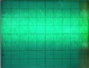
Fig. 3.3.1 CRO Displaying HF Noise
Noise
Noise is any random unwanted signal that is added to the signal being amplified, it is also known as ‘White Noise’ as it typically occurs across the whole bandwidth or frequency spectrum of an amplifier just as white light contains all of the frequencies across the visible light spectrum. Applying negative feedback has the useful effect of reducing noise in amplifiers. However the important word in that sentence is IN, negative feedback does not greatly affect noise introduced before the amplifier input.
Externally Generated Noise and Interference
Externally generated interference (non random noise) includes mains (line) born sources such as spikes of interference caused by arcing contacts when heavy currents are switched. Thyristor and Triac control of mains power can also generate mains born interference as well as interference transmitted by electromagnetic radiation. While most of this type of interference is low frequency, around 50Hz to 120Hz, the widespread use of switch mode power supplies that switch high voltages on and off at high frequency, adds to the spectrum of frequencies where noise may be generated.
Noise may also come from entirely natural sources such ‘static’ noise in the form of hissing and crackling that is continually radiated from space, and atmospheric noise generated by lightning discharges in thunderclouds. Radio frequency amplifiers may also be subject to interference from transmissions broadcasting at similar frequencies to the required signal.
Minimising External Noise
All of this noise or interference can be present at the amplifier input and/or the power supply input in mains/line powered equipment. Because noise and interference occurs over a very wide frequency range, any amplifier (audio, RF VHF etc.) may be affected. As Negative feedback will not eliminate noise from external sources, other steps will be taken in well designed systems to minimise external noise, rather than relying solely on NFB. External noise reduction will use methods such as:
• Efficient screening to minimise electromagnetic and electrostatic interference.
• Good low resistance connections to ground within the amplifier circuit to minimise electromagnetic pickup into circuit wiring.
• Careful placement and electromagnetic shielding of components that may be a cause of noise, such as power transformers and supplies.

Fig. 3.3.2 Extra HF decoupling
• Efficient decoupling and interference suppression of DC power supplies to the circuit to limit mains/line noise and interference.
Extra HF decoupling for amplifier power supplies.
The decoupling circuit in Fig. 3.3.2 is designed to remove any noise present on the power supply lines of a circuit and examples can typically be found wherever supply lines feed circuits that are particularly susceptible to noise, such as amplifiers. Low and medium frequency noise will be removed by the electrolytic capacitor (C1), which has a much lower impedance at these frequencies than the series resistance (R). At higher frequencies, although capacitive reactance (XC) reduces, in electrolytic capacitors at high frequencies XC tends to increase once more, so for efficient high frequency decoupling a polyester capacitor, with typically a medium to high value, is added.
Internally Generated Noise
When all steps have been taken to minimise externally generated noise, there is still the problem of noise generated within the components that make up the amplifier. Transistors, especially bipolar types, will generate noise from a variety of causes including Thermal noise due to molecular agitation of the semiconductor material caused by heat, and ‘Shot noise’, which is caused by charge carriers (electrons and holes) randomly diffusing across the semiconductor junctions. All these types of noise combine to produce a typical background hiss that can be heard from an audio amplifier in the absence of much louder signals.
The presence of internally generated noise is most noticeable when it is generated in the earliest stages of the amplifier, noise produced in the first stage of a series of amplifiers will receive the greatest amplification as it passes through the most stages. For this reason, in many amplifiers, the input stage will use a FET, which produces less junction noise because the current path through the transistor does not cross any PN junctions.
The Role of Negative Feedback
Noise at frequencies above and below the required bandwidth of the amplifier can be reduced by the use of high and low pass filters, but negative feedback can play a part in improving the signal to noise ratio within the bandwidth of an amplifier. The feedback signal from the amplifier output contains both an anti phase portion of output signal and an anti phase sample of any noise generated in the amplifier. When this anti phase noise is added to the input signal, it subtracts from the noise generated within the closed loop, reducing it by a factor of 1+Aβ compared to what it would be without NFB.
Using NFB to reduce noise will not, entirely eliminate, but will reduce noise generated within the amplifier; it will improve a well-designed amplifier but will not eliminate problems on one that is poorly designed.