Op Amp Voltage Amplifiers
- After studying this section, you should be able to:
- Compare ideal and practical op amps.
- Understand the operation of op amps
- • The use of negative feedback.
- • Current rule for op amps.
- • Voltage rule for op amps.
- • The inverting voltage amplifier.
- • The non-inverting voltage amplifier.

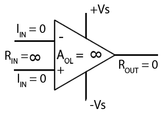
Fig. 6.7.1 The Ideal Op Amp
The Ideal Op Amp
Although the ideal op amp does not exist in reality, a real (practical) op amp comes reasonably close to achieving the ideal. An ideal amplifier should, in addition to other desirable parameters, have at least an infinitely high input impedance, an output impedance of zero ohms, an infinitely high gain and an infinitely wide bandwidth. Table 1 compares some imprtant parameters such as Input Impedance(ZIN), Input Bias Current (IIN),Large Signal Voltage Gain (AV) and Output Impedance (ZOUT) of some typical real (practical) op amps with the ‘ideal’ op-amp model:
| Table 1: The Ideal Amplifier v The Practical Op Amp | ||||
|---|---|---|---|---|
| ZIN | IIN | AV | ZOUT | |
| The Ideal Op-Amp | Infinity. | Zero. | Infinity | 0Ω |
| 741 | 2MΩ | 80nA | 316 to 200,000 (50dB to 106dB) | Depends on gain and feedback but typically less than 100Ω to more than 1KΩ |
| TLC271 | 1TΩ | 60pA | 5,000 to 46,000 (74dB to 93dB) min. | |
| LMC660 | >1TΩ | 0.002pA | 40,000 to 990,000 (92dB to 126dB) | |
Negative Feedback
There are two basic methods of connection for op amp voltage amplifiers, making the op amp into an inverting or a non-inverting voltage amplifier. In each case, the voltage gain of the amplifier is set simply by the ratio of two resistors. Using a very high gain amplifier and applying negative feedback produces a very stable amplifier with a gain that is is virtually independent of changes in temperature or variations in semiconductor characteristics. Just as in the discrete component amplifiers described in Amplifiers Module 3, the negative feedback also reduces distortion and noise in addition to increasing the bandwidth of the amplifier.
Op Amp Rules
Ideal op amps, when used with feedback, operate in a way that can be predicted by a couple of basic rules, often called "Golden Rules".
Rule 1. The Voltage Rule.
The op amp output will change as necessary to keep the two input voltages identical. If any input signal or voltage tries to make the input potentials different, the op amp output will change in the opposite polarity to the input and, via the feedback loop, keep the difference between the two inputs at 0V.
Rule 2. The Current Rule.
Because the input impedance is infinitely high, no current can flow into either input.
These rules used in relation to the ideal op amp can be used to make the operation of the two main voltage amplifier circuits easier to understand. The small differences between ideal and practical op amps can be temporarily ignored.

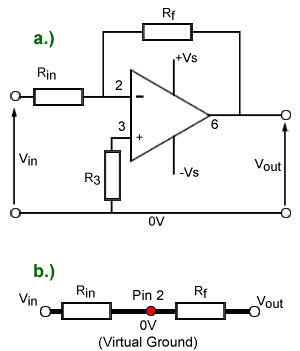
Fig.6.7.3 The Inverting Amplifier
The Inverting Amplifier
Fig. 6.7.3 shows the inverting amplifier, in this configuration the signal input is applied to the inverting (−) input to produce an anti-phase output signal whose amplitude is Vin x Avcl where Avcl is the closed loop gain of the op amp.
Negative feedback is used to reduce the op amp’s very high maximum gain to the required level. The closed loop gain (Avcl) is set simply by the ratio of Rf to Rin
How the Inverting Amplifier Works
By applying the two rules to the ideal op amp shown in Fig. 6.7.3a it can be assumed that:
Pin 3 is at 0V, as it is connected to ground via R3, which will have no voltage developed across it as no current flows into pin 3 (Rule 2), so pin 2 will also be at 0V (Rule 1).
Therefore Rin and Rf are effectively connected in series between Vin and Vout with pin 2 between the two resistors held at 0V.
No current can flow into pin 2 (Rule 2) so the current flowing into Vin cannot be flowing into the op amp, therefore it must be flowing through Rf to the output.
The diagram in Fig. 6.7.3b shows that in effect Rin and Rf are two resistors connected in series between Vin and Vout with Pin 2 at 0V.
Although pin 2 is not actually connected to ground, it must be at the same voltage as pin 3 (Rule 1) which is at 0V (because of Rule 2). This important effect of making some location in a circuit that is not actually connected to ground, yet maintains a potential of 0V is called ‘virtual earth’ (or virtual ground).
Any input current (Iin) therefore flows directly from the input, via Rin and Rf to the output, with Rin and Rf forming a potential divider between the opposite polarity voltages Vin and Vout with pin 2 at 0V.
The current through a series resistor circuit is the same for each resistor, so the input voltage Vin will be proportional to the resistance of Rin and the voltage across Rf will be proportional to the resistance of Rf
Notice that because Rf is effectively connected between the output terminal and virtual earth (0V) the voltage across Rf is also equal to Vout. This makes Rf / Rin equal to Vout / Vin (the gain of the amplifier) and therefore the closed loop gain of the inverting op amp voltage amplifier (Avcl) is given by the equation:

Notice that the formula only tells you the ratio of the resistors and not their actual values. Fortunately in audio amplifiers the values are not too critical, usually keeping the resistor values between about 10K and 100K is OK. However it is good to try and keep Rin as high a resistance as possible, and also in a practical amplifier, rather that grounding the non-inverting input directly it should be grounded by a resistor with the same value as Rin to keep the (tiny) input currents equal. This gives a better chance of the output voltage being zero volts (or close to it) when the input is zero volts.
The Non-inverting Amplifier

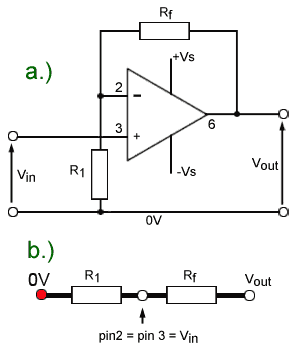
Fig.6.7.4 The Non-Inverting Amplifier
In the non-inverting amplifier illustrated in Fig. 6.7.4a the input is applied to the non-inverting input (pin 3) while the negative feedback resistor (Rf) together with R1 set the closed loop gain of the amplifier.
The input and output signals are now in phase, which changes the circuit operation. As shown in Fig. 6.7.4b, the circuit does not have a virtual earth point, but the bottom end of R1 is connected to ground, which means that pin 2 will follow the varying input voltage Vin on pin 3 (Rule 1).
Rf and R1 now form a potential divider between Vout and 0V. Just like the inverting amplifier, no current will flow into pin 2 (Rule 2) so the voltages across R1 and Rf will be proportional to their individual resistances. The ratio of these resistances, and therefore the ratio of Vout to Vin i.e. the closed loop gain is given by the standard potential divider formula (Rf + R1) / R1.


