Module 2.0
Regulation & Stabilisation
- Section 2.0 Regulation & Stabilisation.
- • Regulation & Stabilisation.
- • Effects of Poor Regulation.
- • The Shunt Regulator.
- • The Series Regulator
- Section 2.1 Shunt Voltage Regulators.
- • The Zener Diode.
- • The Basic Shunt Regulator Circuit.
- • Calculate Component Values.
- • Limitations of the Basic Shunt Regulator Circuit.
- • Improving Current Rating and Line Regulation.
- Section 2.2 Series Voltage Regulators.
- • The Simple Series Regulator.
- • Using Feedback & Error Amplification.
- • Current Limiting.
- • Over Voltage Protection.
- Section 2.3 I.C. Regulators.
- • 78xx Series of Voltage Regulators
- • Decoupling.
- • Dropout.
- • Reliability.
- Section 2.4 Regulated Power Supplies Quiz.
- • Test Your Knowledge of Regulated Power Supplies.

The Regulator/Stabiliser Block
Effects of Poor Regulation
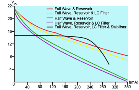
The effect of poor regulation (or stabilisation) of the supply can be seen in Fig. 1.3.1 which shows graphs of output voltage (VDC) for increasing load current (I) in various versions of a basic power supply.
Notice that the output voltage is substantially higher for full wave designs (red and yellow) than half wave (green and purple). Also note the slightly reduced voltage when a LC filter is added, due to the voltage drop across the inductor. In every case in the basic design the output voltage falls in an almost linear fashion as more current is drawn from the supply. In addition to this effect, the extra discharge of the reservoir capacitor also causes the ripple amplitude to increase.

Fig. 1.3.1 Regulation Curves Compared
Regulator (Stabiliser)
Regulator or Stabiliser?
Strictly speaking, compensating for variations in the mains (line) input voltage is called REGULATION, while compensating for variations in load current is called STABILISATION. In practice you will find these terms used rather loosely to describe compensation for both effects. In fact most stabilised or regulated power supplies compensate for both input and output variations and so are both (at least to some degree) stabilised and regulated power supplies.
In common with much modern usage, the term ‘Regulator’ will be used here to describe both regulation and stabilisation.
These problems can be largely overcome by including a regulator stage at the power supply output. The effect of this circuit can be seen in Fig. 1.3.1. as the black line on the graph, where for any current up to about 200mA the output voltage (although lower than the absolute maximum provided by the basic supply) remains constant.
A regulator counteracts the effects of varying load current by automatically compensating for the reduction in output voltage as current increases.
It is also common in regulated supplies, that the output voltage is automatically and suddenly reduced to zero as a safety measure if the current demand exceeds a set limit. This is called Current Limiting.
Regulation requires extra circuitry at the output of a simple power supply. The circuits used vary greatly in both cost and complexity. Two basic forms of regulation are used:
1. The shunt regulator.
2. The series regulator.
These two approaches are compared in Fig. 1.3.2 & Fig 1.3.3
The Shunt Regulator

Fig. 1.3.2 The Shunt Regulator
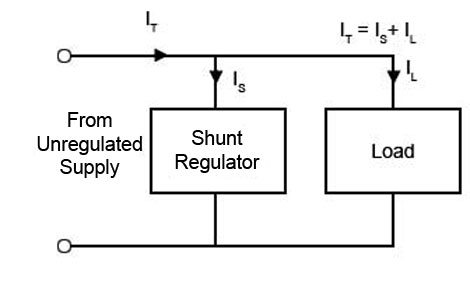
In the shunt regulator (Fig. 1.3.2) , a circuit is connected in parallel with the load. The purpose of the regulator is to ensure a stable voltage across the load at all times; this is achieved by arranging that a current will flow through the regulator circuit at all times. If the load current increases, then the regulator circuit reduces its current so that the total supply current IT, (made up of the load current IL plus the regulator current IS), remains at the same value. Similarly if the load current decreases, then the regulator current increases to maintain a steady total current IT. If the total supply current remains the same, then so will the supply voltage.
The Series Regulator

Fig. 1.3.2 The Series Regulator
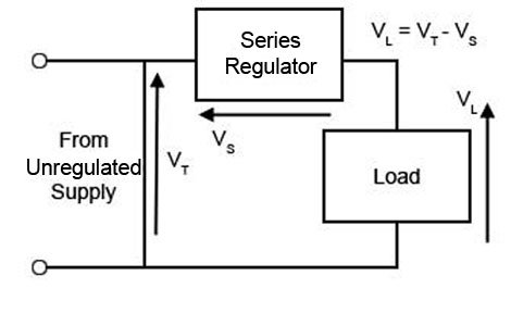
In the series regulator (Fig. 1.3.3), the controlling device is in series with the load. At all times there will be a voltage drop across the regulator. This drop will be subtracted from the supply voltage to give a voltage VL across the load, which is the supply voltage VT minus the regulator voltage drop VS. Therefore:
VL = VT - VS
Series regulators are usually controlled by a sample of the load voltage, using a negative feedback system. If the load voltage tends to fall, the smaller feedback causes the controlling device to lessen its resistance, allowing more current to flow into the load, so increasing the load voltage to its original value. An increase in load voltage will have the opposite effect. Like shunt regulation, the action of the series regulator will also compensate for variations in the supply voltage.


