Google Ads
Module 2.1
Resistor Colour Codes
- After studying this section, you should be able to:
- • Identify values, tolerances & temperature coefficients on colour coded resistors.
- Four band colour code.
- Five band colour code.
- Six band colour code.
Four Band Resistor Colour Code
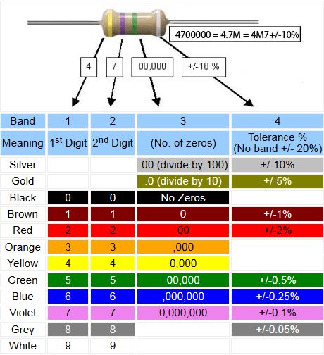
The Colour Codes used on resistors in carbon, carbon film and metal film types are widely used and a ‘must learn’ for electronics engineers. The tables on this page illustrate three common forms for four, five and six band resistors.
In the four band resistor colour code illustrated in Table 2.1.1, the first three bands (closest together) indicate the value in ohms. The first two of these bands indicate two numbers and the third, often called the multiplier band indicates the number of zeros, e.g. red, red, red indicates 2200Ω, which is normally called 2.2KΩ or 2K2. This last version is used in many circuit diagrams and suppliers catalogues (where print may need to be very small) to avoid 2.2K being read as 22K instead of 2K2 where the decimal point may not be obvious. The multiplier band will most commonly be some colour between black (no zeros), indicating a value between10 Ω and a value less than 100Ω, and blue (6 zeros), indicating a value in the tens of millions, e.g. 10,000,000Ω (= brown, black, blue)

Table 2.1.1 Four Band Resistor Colour Code
Two special cases of the multiplier band (band 3) are used for very small values where gold indicates that the first two bands must be divided by 10, and silver means divide by 100, e.g. 4.7Ω (or 4R7) would be indicated by yellow, violet(47), gold (divided by 10) = 4.7Ω.
The fourth band, separated by a space from the three value bands, (so that you know which end to start reading from), indicates the tolerance of the resistor. Gold (+/-5%) and silver (+/-10%) being the most common tolerances.
Notice also that where bands 1, 2 and 3 are black, this would signify a 0Ω resistor, which seems ridiculous as this would virtually be a piece of wire. Actually there is a reason that 0Ω resistors are available; the reason is that where a wire link may be needed on a printed circuit board, it is easier for automated component insertion machines to insert a 0Ω resistor that is the same size and shape as a resistor, rather than have to use another process to insert a wire link. Also this resistor can easily be changed for a different value where different versions of a circuit may be built, using the same PCB. The tolerance band on a resistor indicates the spread of possible values of any particular resistor, for example a resistor marked as 47KΩ +/- 10% will have an actual value somewhere between 42.3KΩ and 51.7KΩ

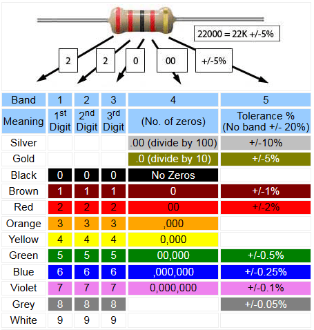
Table 2.1.2 Five Band Resistor Colour Code
Five Band Resistor Colour Code
Resistors are available in several different versions of ‘Preferred Values’ as explained Resistors & Circuits Module 2.2. Some of these versions contain a wider range of values, requiring a more accurate numerical value and closer tolerance ratings than can be achieved in the four band colour code. Therefore the five band code (Table 2.1.2) was created to accommodate this greater accuracy; most resistors in this series having a tolerance rating of +/-1% or +/-2%. Other tolerance values are shown for completeness.

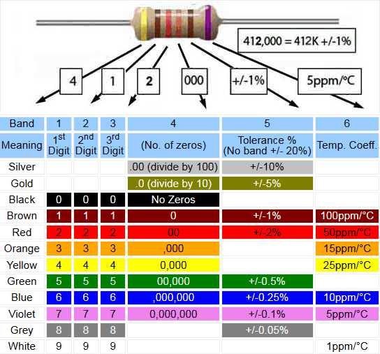
Table 2.1.3 Six Band Resistor Colour Code
6 Band Colour Code
The six band code adds another column to accommodate the temperature coefficient, which defines the likely change in resistor value per °C, between its value over specified temperature range. In general, carbon resistors have a negative temperature coefficient and so will reduce their resistance as they heat up, metal film resistors however may be found to have either a positive or a negative temperature coefficient, depending on the manufacturer‘s choice of metals, the aim being to produce a resistor whose temperature coefficient, and so any variation in value is as close to zero as possible. Such changes in resistance are normally very small and measured in parts per million, e.g. 50ppm/°C. Therefore it can be calculated from Table 2.1.3 that a 1MΩ resistor having a +/-2% tolerance (red band 5) might be expected to change its value by 1000Ω when its temperature changes by 20°C. Notice that this is still well within the resistor’s +/-2% tolerance, which would be +/- 20KΩ
Google Ads


