Google Ads
Module 5.4
Opto Activated Switches
- After studying this section, you should be able to:
- Recognise opto controlled switches.
- Describe applications for typical opto switches:
- • Slotted optical switches.
- • Reflective optical switches.
- Design simple circuits employing opto switches:
Fig. 5.4.1 Slotted Optical Switch (a)
and Reflective Object Sensor (b)
Two typical opto activated switches are illustrated in Fig. 5.4.1. Example (a) is a slotted switch where a beam of infrared light from the LED illuminates a phototransistor, causing it to conduct. When an object is moved into the slot between the LED and phototransistor the light is interrupted and the phototransistor switches off. Opto activated switches are normally operated in saturation mode to provide definite on and off signals.
Another common application for slotted switches is to have a rotating disc, with slots or holes around its rim to spin within the light path of the switch, thereby creating a series of on/off pulses that can be used to indicate (and electronically control) the speed of the spinning disc.
In the reflective object sensor illustrated in Fig. 5.4.1(b) the infrared LED and the phototransistor are mounted side by side in the narrow end of the switch. Here, a beam of infrared light is emitted at an angle by the LED and if some reflective material is placed about 3 to 4mm from the sensor, the light beam from the LED is reflected back onto the phototransistor causing it to conduct and produce an output current. This arrangement is often used as a proximity sensor.
The phototransistor in proximity sensors also operates in 'saturation mode' where the phototransistor is caused to be either off (passing no current) or on (fully saturated, passing its maximum current) by the action of the reflected infrared light.
Slotted Optical Switch Example
Fig. 5.4.3 Slotted Optical Switch
Circuit
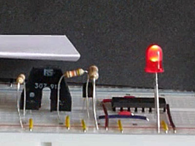
A simple example of a slotted optical switch is shown in Fig 5.4.2, with its schematic diagram in Fig. 5.4.3. When an object such as a ticket, or a small tab that is part of some mechanical system is placed in the sensor slot, the beam of infrared light from the LED to the phototransistor is blocked, turning off the phototransistor. Its emitter terminal, which has been at a high voltage of about 4.8V because the phototransistor has been in saturation and therefore conducting heavily, turns off and the emitter voltage falls to a low value of around 0.8V.
This turns off the 2N3904, which causes its emitter to fall to around 0.3V. This is seen as a logic 0 at pin 1 of IC2 (the input of one of the 6 Schmitt inverters in the IC) and its output at pin 2 changes to logic 1, lighting the green 5V LED. Removing the object from the slotted switch allows the infrared light to reach the base of the phototransistor causing it to conduct and saturate again, which now has a voltage of nearly 5V at its emitter. This switches on the 2N3904 causing a logic 1 (a voltage greater than 2V) to appear at its emitter and the Schmitt inverter input. This turns on the red LED and turns the green LED off.
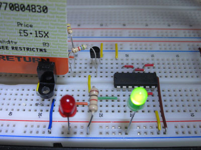
Fig. 5.4.2 Slotted Opto Switch in Operation
Fig. 5.4.2 Slotted Opto Switch Sensing a Ticket
The Opto Slotted Switch Interface
The input LED of the slotted OPB370 switch chosen for this demonstration has a maximum current rating of 50mA and the data sheet for the OPB370 shows that at 20mA the forward voltage of the LED will be about 1.3V. To provide a reasonably bright illumination from the LED, it is driven via R1 with IF at about 37mA.
The aim of this design is to drive a single input of a HCT Schmitt inverter gate, which will be responsible for ultimately providing an output that will have very fast rise and fall times and standard HCT voltage and current parameters.
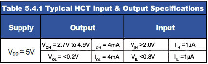
As can be seen in Table 5.4.1, the HCT Schmitt gate will recognise a voltage above 2.0V (VIH) as logic 1 and a low voltage (VIL) below 0.8Vas logic 0. The output current from the 2N3904 must also be sufficient to drive the HCT inverter input, and anything between 1µA and 4mA will be enough.
R1 in the circuit is the current limiting resistor for the input LED and is chosen here to provide a current of about 37mA through the infrared input LED. Note also that the optional 5V LEDs (D1 and D2) used here have an internal current limiting resistor, but a 'normal' LED with appropriate external current limiting resistor could also be used.
Although phototransistor optocouplers produce many times the current produced by photodiode types the output from the phototransistor is still very small and is therefore further amplified by the 2N3904. In addition the 7414 Schmitt inverter provides further conditioning to make the output rise and fall times very fast, and the voltage and current levels ideal for driving HCT digital circuitry. The voltages shown in Fig. 5.4.4 were taken from the working breadboard example shown in Fig. 5.4.2.
Fig. 5.4.4 Opto Proximity Sensor Circuit
Reflective Object (Proximity) Sensor
These optical sensors work in a similar way to the slotted opto sensor but rely on infra red light reflected from an object (e.g. a sheet of paper in a printer) placed about 2mm to 8mm from the sensor to produce an output. The current produced by the sensor is even smaller than the output currents of the Slotted Switch and therefore also needs to be amplified by a transistor buffer stage to be useful, as shown in Fig. 5.4.4.
A Schmitt Inverter is also added to the output to ensure rapid changes in logic level as a reflective object is detected within the detection range. To avoid sensing errors these sensors work best in low ambient light levels, where the only light sensed by the phototransistor is the reflected light from the infra red LED.
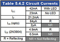
Notice also in both of these switching circuits that only one power source is being used, as electrical isolation between input and output is normally less important. The input to these sensors is light rather than some electrical property. The output is HCT logic, making it suitably conditioned for input to many computer or logic circuit applications. Typical voltages are shown in Fig.5.4.4 and current values in Table 5.4.2
Proximity Detector Circuit Operation
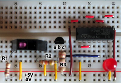
Fig. 5.4.5 Opto Proximity Sensor
Breadboard Layout
R1 is the current limiting resistor for the infrared LED and sets the LED current (IF)at approximately 20mA. The infra red light produced is reflected from an object (plain white printer paper was used in tests) and when in the detection range of about 2mm to 8mm produces a current though R2 of up to about 64µA, dropping to almost zero with no object present (and low ambient light levels).
This current is sufficient to turn on the 2N3904 buffer amplifier transistor and its collector voltage falls from nearly Vcc to almost 0V.
These changes depend on the amount of light reflected into the sensor so may not be fast to change and can be of variable amplitude, however the Schmitt inverter will provide a very fast transition from low to high or high to low at any time the collector voltage of the 2N3904 transistor passes the inverter's threshold values.
Where only a single sensor is required, the use of only 1 out of 6 inverters in the 7414 IC may seem wasteful. The circuit will work without the 7414 inverter, but the switching is much less definite and the output is high without a reflective object being present and low when reflection occurs.
For test purposes, a 5V red LED (with internal current limiting resistor) was used to give a clear indication of the circuit operation. However this can be left out when the circuit is used as an input to another circuit as this will considerably reduce the supply current required, as shown in Table 5.4.2.
The original test circuit is shown in Fig. 5.4.5. Notice that the normally invisible infra red LED shows up as visible (purple) light on a digital camera. Also note that as only the inverter connected between pins 5 and 6 of the IC are being used, the five other unused inputs on the 7414 IC are all connected to 0V to prevent excessive noise being injected into the circuit.