Google Ads
Module. 2.3
Capacitance
- • What is capacitance?
- • Dielectric.
- • permittivity.
- • Dielectric strength and maximum working voltage.
- • Calculating the charge on a capacitor.
Capacitance
The amount of energy a capacitor can store depends on the value or CAPACITANCE of the capacitor. Capacitance (symbol C) is measured in the basic unit of the FARAD (symbol F). One Farad is the amount of capacitance that can store 1 Coulomb (6.24 x 10¹⁸ electrons) when it is charged to a voltage of 1 volt. The Farad is much too large a unit for use in electronics however, so the following sub-units of capacitance are more useful.
| Sub unit | Abbreviation | Standard notation |
|---|---|---|
| micro Farads | µF | x 10-6 |
| nano Farads | nF | x 10-9 |
| pico Farads | pF | x 10-12 |
Remember however, that when working out problems involving capacitance, the formulae, the values used must be in the basic units of Farads, Volts etc. Therefore when entering a value of 0.47nF for example, into a formula (or your calculator) it should be entered in Farads using the Engineering Notation version of Standard Form as: 0.47 x 10⁻⁹ (Download our Maths Tips booklet for more information).
Capacitance depends on four things;
1.The area of the plates
2.The distance between the plates
3.The type of dielectric material
4.Temperature
Of these four, temperature has the least effect in most capacitors.The value of most capacitors is fairly stable over a "normal" range of temperatures.
Capacitor values may be fixed or variable. Most variable capacitors have a very small value a few tens or hundreds of pF) The value is varied by either:
- •Changing the area of the plates.
- •Changing the thickness of the dielectric.
Capacitance (C) is DIRECTLY PROPORTIONAL TO THE AREA OF THE TWO PLATES that directly overlap, the greater the overlapping area, the greater the capacitance.
Capacitance is INVERSELY PROPORTIONAL TO THE DISTANCE BETWEEN THE PLATES. i.e. if the plates move apart, the capacitance reduces.
The Dielectric
The electrons on one plate of the capacitor affect the electrons on the other plate by causing the orbits of the electrons within the dielectric material (the insulating layer between the plates) to distort. The amount of distortion depends on the nature of the dielectric material and this is measured by the permittivity of the material.
Permittivity
Permittivity is quoted for any particular material as RELATIVE PERMITTIVITY, which is a measure of how efficient a dielectric material is. It is a number without units which indicates how much greater the permittivity of the material is than the permittivity of air (or a vacuum), which is given a permittivity of 1 (one). For example, if a dielectric material such as mica has a relative permittivity of 6, this means the capacitor will have a permittivity, and so a capacitance, six times that of one whose dimensions are the same, but whose dielectric is air.
Dielectric Strength
Another important aspect of the dielectric is the DIELECTRIC STRENGTH. this indicates the ability of the dielectric to withstand the voltage placed across it when the capacitor is charged. Ideally the dielectric must by as thin as possible, so giving the maximum capacitance for a given size of component. However, the thinner the dielectric layer, the more easily its insulating properties will break down. The dielectric strength therefore governs the maximum working voltage of a capacitor.
Maximum Working Voltage (VDCwkg max)
It is very important when using capacitors that the maximum working voltage indicated by the manufacturer is not exceeded. Otherwise there will be a great danger of a sudden insulation breakdown within the capacitor. As it is likely that a maximum voltage existed across the capacitor at this time (hence the breakdown) large currents will flow with a real risk of fire or explosion in some circuits.
Charge on a Capacitor.
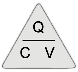
The charge (Q) on a capacitor depends on a combination of the above factors, which can be given together as the Capacitance (C) and the voltage applied (V). For a component of a given capacitance, the relationship between voltage and charge is constant. Increasing the applied voltage results in a proportionally increased charge. This relationship can be expressed in the formula;

Q = CV
or
C = Q/V
or
V = Q/C
Where V is the voltage applied, in Volts.
C is the capacitance in Farads.
Q is the quantity of charge in Coulombs.
So any of these quantities can be found provided the other two are known. The formulae can easily be re-arranged using a simple triangle similar to the one used for calculating Ohm´s Law when carrying out resistor calculations.


