Google Ads
Module 11.2
Magnetic Circuits and Transformer Cores.
- After studying this section, you should be able to describe:
- • Magnetic Flux.
- • Permeability: relative and absolute.
- • Reluctance.
- • The Magnetic Circuit.
- • Magneto-motive force, m.m.f.
- • Common types of transformer cores.
Magnetic Flux and Ampere Turns
The strength of the magnetic field (or amount of flux measured in Webers) in a transformer core is directly proportional to the number of TURNS around the coil that is producing the magnetic flux within the core, and to the amount of CURRENT flowing in the coil. Therefore the amount of flux, Φ (The Greek letter Phi) is proportional to the product of N (number of turns) x I (the current in amperes) or the 'AMPERE TURNS' of the coil. Increasing either the number of turns or the current in the coil produces an increase in flux.
Reluctance.
There is a third way to increase the flux. That is to improve the magnetic properties of the core by using a material that has a low Reluctance (Rm), this is the property of a material that is the magnetic equivalent of the electrical property of Resistance. The lower the reluctance, the easier it is for magnetic flux to flow through the core material.
Materials that are easily magnetised have a low reluctance and a high permeability, and non-magnetic materials have a high reluctance and a low permeability. The opposite of Reluctance is Permeability, the magnetic equivalent of electrical Conductance.
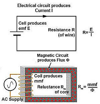
Fig 11.2.1
Electrical and Magnetic Circuits compared.
Electrical and magnetic circuits are similar in many respects. Fig. 11.2.1 compares a simple electrical and simple magnetic circuit.
In the electrical circuit an emf produced by a cell or battery drives a current around the circuit, which consists of a length of wire having some resistance R.
The magnetic circuit also has a source of magnetic power in the form of a coil, supplied with an AC current. Just as the external electrical source is called an electro motive force, the external magnetic source is called a magneto motive force (mmf), and is measured in ampere turns.
An emf produces a current (I), which has a strength measured in amperes in the electrical circuit; in the magnetic circuit, the mmf produces a magnetic flux, Φ and is measured in units of webers (Wb). The resistance to the flow of magnetic flux in the core is called Reluctance ( Rm )
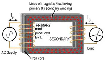
Fig 11.2.2
Magnetic Flux linking primary and secondary windings.
Figure 11.2.2 shows a magnetic circuit made from a rectangular shaped iron loop or core. A coil (the primary) supplied with an AC current is wound around one side of the core to provide a source of mmf. On the other side of the core a separate coil (the secondary) is wound, which supplies a measuring instrument to measure the amount of current in the coil. The current in this coil will be proportional to the amount of flux flowing in the core. This arrangement therefore provides a means of measuring magnetic flux.
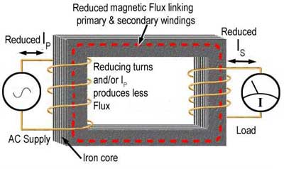
Fig 11.2.3
Fig 11.2.3 Flux is proportional to current and number of turns.
Figure 11.2.3 shows that by changing the number of turns on the primary coil, or the current through it, a different amount of current will flow in the secondary coil showing that the flux (Φ) is proportional to both the current and the number of turns.
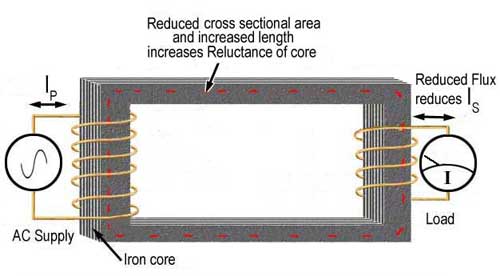
Fig 11.2.4
Fig 11.2.4 Flux is also affected by the dimensions of the core.
Figure 11.2.4 shows that if the mmf is kept constant, but the dimensions of the core are altered by changing either the length of the flux path or its cross sectional area, the amount of flux flowing around the core will also change.
Therefore the measured flux (Φ) in the core (and therefore the secondary current) is proportional to the cross sectional area of the core, and inversely proportional to the length of the flux path:
Where:
A is the cross sectional area of the core and
L is the mean length of the flux path around the core.
The magnetic circuit also has some Reluctance Rm (a type of resistance to flux);

Reluctance is measured in Amperes per Weber (A/Wb).
Permeability.
Electrical resistance also depends not only on the dimensions of the conductor but also on the material of the conductor and its resistivity. Likewise, in magnetic circuits reluctance depends not only on the length and cross sectional area, but also on the Permeability (µ) of the material.
The higher the value for µ the more flux will flow and the more flux that flows, the lower must be the value of reluctance Rm
Therefore:

So Reluctance increases with the length of the magnetic path (l) and decreases as either the cross sectional area (A) of the core or the Permeability (µ) of the material is increased.
Relative and Absolute Permeability
Permeability is often expressed as:
µ = µ0 µr
It is normal to find a core material described by its relative permeability (µr ), i.e. by how many times the absolute permeability (µ) of the material is greater than the absolute permeability of free space (µ0 ). The absolute permeability of free space µ0 has a value of 4p x 10 -7 H/m = 1.256637061 x 10 -6 H/m where H is in henrys and m is in metres. Quoting the absolute permeability of materials used in cores would involve similarly awkward numbers. If a more convenient figure, the relative permeability of free space (or air), which will be 1 is used, the absolute permeability of a material (µ) will be its relative permeability (µr ) multiplied by the absolute permeability of free space (µ0 ).
Therefore µ is a simple ratio that does not have any units, e.g. if the µ of a material is given as 1000, its permeability is one thousand times greater than the absolute permeability of free space (or air).
The permeability of iron can be many hundreds, so having a magnetic circuit path of iron rather than air greatly increases the flux, which is why iron is a common choice of material for inductor and transformer cores.
Fig. 11.2.5. Common Types of Transformer Cores.
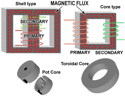
Fig 11.2.5
Fig 11.2.5 illustrates some commonly used types of core. The Shell Core is an improvement of the Core type; its magnetic circuit encloses the windings more fully. Notice the centre limb has twice the cross sectional area of the outer limbs, allowing for double the flux within the primary and secondary windings.
The Toroidal core gives an even more efficient coupling, and radiates less electromagnetic energy outside the transformer.
The magnetic circuit of the two part Pot Core, used for smaller high frequency transformers and inductors, totally encloses the windings.


