Module 5.3
Class B Power Amplifiers
- After studying this section, you should be able to:
- Understand the operation of class B power amplifiers.
- • Class B biasing.
- • Push-pull operation
- Understand crossover distortion.
- • Causes and effects.
- List advantages and disadvantages of class B amplifiers.

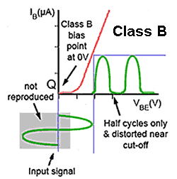
Fig 5.3.1 Class B Bias
Class B
In amplifiers using class B bias, illustrated in Fig. 5.3.1, there is no standing bias current (the quiescent current is zero) and therefore the transistor conducts for only half of each cycle of the signal waveform. This dramatically increases efficiency, compared with class A. Theoretically nearly 80% efficiency can be achieved with this bias and in practical circuits, efficiencies of 50% to 60% are possible.
The downside for this increased efficiency is that the transistor only amplifies half the waveform, therefore producing severe distortion. However, if the other half of the waveform can be obtained in some other way without too much distortion, then class B amplifiers can be used to drive most types of output device. The aim is to obtain a good power gain with as much of the energy consumed from the power supply going into the load as possible. This should be as consistent with reasonable linearity (lack of distortion), as possible. Power output stages do however produce more distortion than do voltage or current amplifiers.
RF Power Amplifiers Using Class B

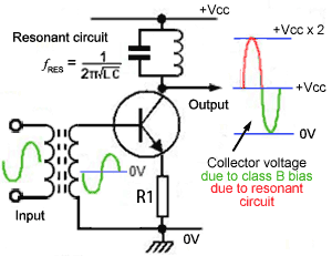
Fig 5.3.2 Class B Radio Frequency
(RF) Power Amplifier
The circuit in Fig 5.3.2 shows how class B bias can be used in a radio frequency (RF) output stage. Although the circuit would produce severe distortion as only half of the signal wave form produces a current in the load, because the load in this case is a tuned circuit resonating at the signal frequency, the resonating effect of the tuned circuit ‘fills in’ the missing half cycles. This method is only suitable at RF, as at lower frequencies the inductors and capacitors needed for the resonant circuit would be too large and costly for most applications. Because of the superior efficiency of class B it is a popular choice for power amplifiers, but to overcome the severe distortion caused by class B, audio amplifiers use a push-pull circuit.
Class B Push Pull Outputs

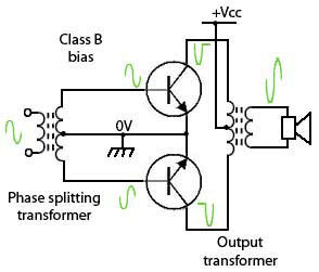
Fig 5.3.3 Class B Push-Pull Output
At lower (e.g. audio) frequencies, a common way to reduce the distortion due to the ‘missing half cycle’ in class B outputs, is to use a push-pull output stage. The principles of this circuit are shown in Fig. 5.3.3. Two identical but anti phase signals from a phase splitter are fed to the bases of a pair of power transistors so that each transistor (conducting only when the half cycle during which its input wave goes positive), feeds current to the load for that half cycle. The two half cycles are reh-combined in this circuit via a centre tapped transformer, which reverses the action of the phase splitter transformer, to produce a complete sine wave in the secondary.
Crossover Distortion

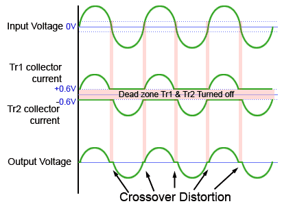
Fig 5.3.4 Crossover Distortion
The main problem with class B push pull output stages is that each transistor conducts for NOT QUITE half a cycle. As shown in Fig. 5.3.4 distortion occurs on each cycle of the signal waveform as the input signal waveform passes through zero volts. Because the transistors have no base bias, they do not actually begin to conduct until their base/emitter voltage has risen to about 0.6V. As a result, there is a ‘Dead Zone’ of about 1.2V around the zero volts line (between −0.6V and +0.6V) where the signal waveform is not amplified, causing a "missing" section from the output signal, resulting in unwanted distortion during the "crossover" from one transistor to the other.
The effect of this distortion on the output depends to some degree on the amplitude of the output signal, the larger the amplitude the less significant the missing 1.2 volts becomes. Also the distortion will be less severe at high frequencies where the rate of change of the wave, as it passes through zero is much faster, causing a shorter ‘step’ in the waveform.
The large and varying current drawn by a powerful class B amplifier also puts considerable extra demand on the DC power supply and as the current drawn varies with the amount of signal applied, the smoothing capabilities of the power supply must be efficient enough to prevent this varying current from creating voltage changes at audio frequencies on the power supply lines. If these are not adequately removed, unintended audio feedback into earlier amplifier stages can occur and cause problems with instability. This extra demand on power supply complexity adds to the cost of class B power amplifiers.
| Class B | |
|---|---|
| Advantages | Disadvantages |
| Very low standing bias current. Negligible power consumption without signal. | Creates Crossover distortion. |
| Can be used for much more powerful outputs than class A | Supply current changes with signal, stabilised supply may be needed. |
| More efficient than Class A. | More distortion than Class A. |
Crossover distortion is more of a problem in low and medium power class B amplifiers and the method used to eliminate it, is to use a class B amplifier that has some bias (and quiescent current) added so that the output transistors are conducting continually, and so avoiding the ‘dead zone’ of class B. As this method has some properties of both class A and class B it is called Class AB.


