Module 5.6
Amplifier Classes C to H
- After studying this section, you should be able to:
- Understand the differences between amplifier classes A to H:
- • Class C bias.
- Understand the operation of class D amplifiers & the need for:
- • Pulse width modulation.
- • Power switching.
- • Output Filtering.
- Understand the basic operation of classes E and F.
- Understand the basic operation of classes G and H.
Alternative Amplifier Classes
The class A Common Emitter Voltage Amplifier described in Amplifier Module 1, Module 2 and Module 3 has some excellent properties that make it useful for many amplification tasks, however it is not suitable for every purpose. Class A biasing is good at preserving the original wave shape as the transistor is biased using the most linear part of the transistor’s characteristics. However the big problem with class A is its poor efficiency. Amplifiers Module 5.3 explains how push-pull class B power amplifiers improve efficiency at the expense of added crossover distortion.
Class AB power amplifiers, described in Module 5.5 largely address the problem of crossover distortion by combining elements of both class B and class A design but in doing so, again reduces efficiency. Although class AB is fine for what today would be considered low, or at best medium power amplifiers, the trend in recent years has been to make amplifiers more and more powerful, and where once 30W would have been considered quite adequate to fill a fairly large auditorium, it is now hardly enough for the car stereo! As a result, new classes of amplifier have been created to cope with this high power requirement.

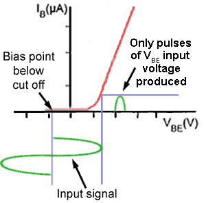
Fig. 5.6.1 Class C Bias
Class C Bias
In Class C, the bias point is placed well below cut-off as shown in Fig.5.6.1 and so the transistor is cut-off for most of the cycle of the wave. This gives much improved efficiency to the amplifier, but very heavy distortion of the output signal. Class C is therefore not suitable for audio amplifiers. It is however commonly used in high frequency sine wave oscillators and certain types of RF amplifiers, where the pulses of current produced at the amplifier output can be converted to complete sine waves of a particular frequency by the use of LCR resonant circuits.
Class D Amplifiers

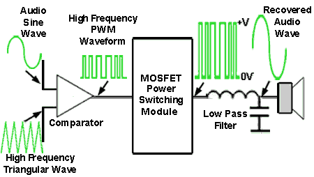
Fig. 5.6.2 Basic Principles of Class D
In class D audio amplifiers, the basic operation of which is shown in Fig. 5.6.2, the audio signal is first converted to a type of digital signal called ‘Pulse Width Modulation’. This is not a digital signal within the normally accepted definition of ‘Digital’ regarding recognised logic 1 and 0 levels, but only in that it has two levels, high and low. When such a signal is amplified, very little power is dissipated in the amplifier, as when the output transistors are ‘on’ and passing their maximum current, there is practically no voltage drop across them and therefore (as Power = Voltage x Current) there is practically zero Power. Likewise, when the transistors are ‘off’, a large voltage is present but no current is flowing. This results in much greater efficiency than in conventional analogue amplifiers. The PWM output signal is finally converted back into analogue form at the output.
Pulse Width Modulation

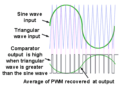
Fig. 5.6.3 Class D Operation
Fig. 5.6.3 illustrates how the audio signal is converted into a ‘pulse width modulated’ form using a comparator, which compares the audio signal, made up of relatively low frequency sine waves, with a much higher frequency triangular waveform. The output of the comparator switches to a high level if the instantaneous voltage of the triangular wave is higher than that of the audio wave, or to a low level if it is lower.
The comparator output therefore consists of a series of pulses whose widths vary in relation to the instantaneous voltage of the sine wave. The average level of the PWM signal has the same shape (though inverted in this case) as the original audio signal.
Fast Power Switching
This PWM output then drives a switching circuit that uses fast switching MOSFET power transistors to switch the output between the full supply voltage (+V) and zero volts (0V). Representing the audio by a series of square pulses dramatically reduces power consumption. When the square wave is at its high level, the transistor is cut-off and although a high voltage is present, virtually no current is flowing, and as power is voltage x current, power is just about zero. During the time when the square wave signal is at its low level, there will be a large current flowing but the signal voltage is practically zero, so again, very little power dissipation. The only time when significant power is dissipated by the MOSFET transistors is during the change from high to low or low to high states. Because high speed switching MOSFETs are used, this period is extremely short, so average power dissipation is kept to a very low level.
Output Filtering
Finally the high frequency, large amplitude PWM pulses are applied to a low pass filter, which removes the high frequency components of the waveform, leaving just the average level of the PWM wave, which because of the varying ‘on’ time of the pulses produces a large amplitude replica of the original sine wave audio input.
Class D operation makes the output circuit extremely efficient (around 90%) allowing high power output without the need for such high power transistors and elaborate heat-sinks. However this big increase in efficiency is only achieved at the expense of some increase in distortion and especially of noise, in the form of electromagnetic interference (EMI).
Because class D produces high frequency, large amplitude PWM ‘square’ waves at the output of the switching module, there will be many large amplitude odd harmonics present, which are a natural component of square waves. The frequencies of these harmonics can extend well into the radio frequency spectrum, and if not carefully controlled can cause radio interference radiated both directly, and conducted via the power supply.
As shown in Fig. 5.6.2 the PWM output is fed to the load via a low pass filter, which should remove the interference causing harmonics, however even with a good quality low pass filter all the harmonics causing interference cannot be removed from the square wave, as this would distort the square wave, and consequently the audio output.
Nevertheless, class D is a very efficient class of amplifier suited to both high power audio and RF amplifiers and low power portable amplifiers, where battery life can be considerably extended because of the amplifier’s high efficiency. The increased interest in class D amplifiers has led to a number of class D integrated circuits becoming available, such as the 25 watts per channel stereo power amplifier TPA3120D2 from Texas Instruments and the 2 watts per channel digital input audio amplifier SSM2518 from Analogue Devices, suitable for mobile phones and portable mp3 players.
Classes E to H
Amplifier classes such as E and F are basically enhancements of class D, offering more complex and improved output filtering, including some additional wave shaping of the PWM signal to prevent audio distortion. Classes G and H offer enhancements to the basic class AB design. Class G uses multiple power supply rails of various voltages, rapidly switching to a higher voltage when the audio signal wave has a peak value that is a higher voltage than the level of supply voltage, and switching back to a lower supply voltage when the peak value of the audio signal reduces. By switching the supply voltage to a higher level only when the largest output signals are present and then switching back to a lower level, average power consumption, and therefore heat caused by wasted power is reduced. Class H improves on class G by continually varying the supply voltage at any time where the audio signal exceeds a particular threshold level. The power supply voltage tracks the peak level of the signal to be only slightly higher than the instantaneous value of the audio wave, returning to its lower level once the signal peak value falls below the threshold level again. Both classes G and H therefore require considerably more complex power supplies, which adds to the cost of implementing these features.


