Module 1.6
Binary Coded Decimal (BCD)
- After studying this section, you should be able to:
- Understand binary coded decimal.
- • 4 bit BCD codes.
- • Converting between binary and BCD.
- • Converting between BCD and decimal.
- • Compare BCD codes with different weighting.
- Understand Gray Code.
- • Composition of Gray Code.
- • Gray Coded Disks.
Representing Decimal Numbers
When calculations are carried out electronically they will usually be in binary or twos complement notation, but the result will very probably need to be displayed in decimal form. A binary number with its bits representing values of 1, 2, 4, 8, 16 etc. presents problems. It would be better if a particular number of binary bits could represent the numbers 0 to 9, but this doesn’t happen in pure binary, a 3 bit binary number represents the values 0 to 7 and 4 bit represents 0 to 15. What is needed is a system where a group of binary digits can represent the decimal numbers 0-9, and the next group 10-90 etc.
To make this possible, binary codes are used that have ten values, but where each value is represented by the 1s and 0s of a binary code. These special ‘half way’ codes are called BINARY CODED DECIMAL or BCD. There are several different BCD codes, but they have a basic similarity. Each of the ten decimal digits 0 to 9 is represented by a group of 4 binary bits, but in codes the binary equivalents of the 10 decimal numbers do not necessarily need to be in a consecutive order. Any group of 4 bits can represent any decimal value, so long as the relationship for that particular code is known.
In fact any ten of the 16 available four bit combinations could be used to represent 10 decimal numbers, and this is where different BCD codes vary. There can be advantages in some specialist applications in using some particular variation of BCD. For example it may be useful to have a BCD code that can be used for calculations, which means having positive and negative values, similar to the twos complement system, but BCD codes are most often used for the display of decimal digits. The most commonly encountered version of BCD binary code is the BCD8421 code. In this version the numbers 0 to 9 are represented by their pure binary equivalents, 4 bits per decimal number, in consecutive order.
BCD Codes
The BCD8421 code is so called because each of the four bits is given a ‘weighting’ according to its column value in the binary system. The least significant bit (lsb) has the weight or value 1, the next bit, going left, the value 2. The next bit has the value 4, and the most significant bit (msb) the value 8, as shown in Table 1.6.1.
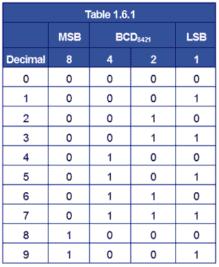
So the 8421BCD code for the decimal number 610 is 01108421. Check this from Table 1.6.1.
For numbers greater than 9 the system is extended by using a second block of 4 bits to represent tens and a third block to represent hundreds etc.
2410 in 8 bit binary would be 00011000 but in BCD8421 is 0010 0100.
99210 in 16 bit binary would be 00000011111000002 but in BCD8421 is 1001 1001 0010.
Therefore BCD acts as a half way stage between binary and true decimal representation, often preparing the result of a pure binary calculation for display on a decimal numerical display. Although BCD can be used in calculation, the values are not the same as pure binary and must be treated differently if correct results are to be obtained. The facility to make calculations in BCD is included in some microprocessors.
One of the main drawbacks of BCD is that, because sixteen values are available from four bits, but only ten are used, there are several redundant values whichever BCD system is used. This is wasteful in terms of circuitry, as the fourth bit (the 8s column) is under used.
Try some simple conversions between Decimal and BCD8421
32110 to BCD8421
6523110 to BCD8421
001101110110 BCD8421 to decimal.
0011001011000110 BCD8421 to decimal.

Fig. 1.6.1 Seven Segment Display
Display Decoder/Drivers
Depending on the type of display some further code conversion may also be needed. One popular type of decimal display is the 7 segment display used in LED and LCD numerical displays, where any decimal digit is made up of 7 segments arranged as a figure 8, with an extra LED or LCD dot that can be used as a decimal point, as shown in Fig 1.6.1. These displays therefore require 7 inputs, one to each of the LEDs a to g (the decimal point is usually driven separately). Therefore the 4 bit output in BCD must be converted to supply the correct 7 bit pattern of outputs to drive the display.
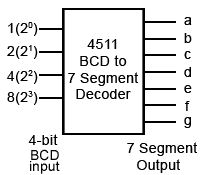
Fig. 1.6.2 Driving a 7 Segment Display
The four BCD bits are usually converted (decoded) to provide the correct logic for driving the 7 inputs of the display by integrated circuits such as the HEF4511B BCD to 7 segment decoder/driver from NXP Semiconductors and the 7466 BCD to 7 segment decoder.
Question
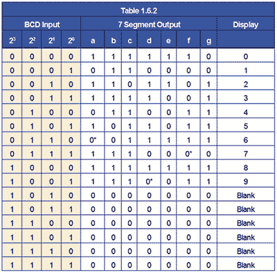
BCD to 7 segment decoders implement a logic truth table such as the one illustrated in Table 1.6.2. There are different types of display implemented by different types of decoder, notice in table 1.6.2 that some of the output digits* may be either 1 or 0 (depending on the IC used). Why would this be, and what effect would it have on the display?
Notice that the 4 bit input to the decoder illustrated in Table 1.6.2 can, in this case, be in either BCD8421 or in 4 bit binary as any binary number over 9 will result in a blank display.
Alternative BCD Codes
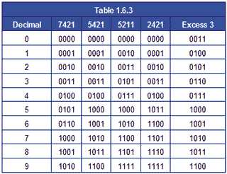
Although BCD8421 is the most commonly used version of BCD, a number of other codes exist using other values of weighting. Some of the more common variations are shown in Table 1.6.3. The weighting values in these codes are not randomly chosen, but each has particular merits for specific applications. Some codes are more useful for displaying decimal results with fractions, as with financial data. With others it is easier to assign positive and negative values to numbers. For example with Excess 3 code, 310 is added to the original BCD value and this makes the code ‘reflexive’, that is the top half of the code is a mirror image and the complement of the bottom half, 5211 code is also self-complementing in this way. Some values in these BCD codes can also have alternative 1 and 0 combinations using the same weighting and are designed to improve calculation or error detection in specific systems.
Gray Code
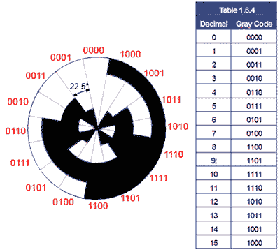
Fig. 1.6.3 Four Bit Gray Code Disk
Binary codes are not only used for data output. Another special binary code that is extensively used for reading positional information on mechanical devices such as rotating shafts is Gray Code. This is a 4 bit code that uses all 16 values, and as the values change through 0-1510 the code‘s binary values change only 1 bit at a time, (see Table 1.6.4). The binary values are encoded onto a rotating disk (Fig. 1.6.3) and as it rotates the light and dark areas are read by optical sensors.
As only one sensor sees a change at any one time, this reduces errors that may be created as the sensors pass from light to dark (0 to 1) or back again. The problem with this kind of sensing is that if two or more sensors are allowed to change simultaneously, it cannot be guaranteed that the data from the sensors would change at exactly the same time. If this happened there would be a brief time when a wrong binary code may be generated, suggesting that the disk is in a different position to its actual position. The one bit at a time feature of gray code effectively eliminates such errors. Notice also that the sequence of binary values also rotates continually, with the code for 15 changing back to 0 with only 1 bit changing. With a 4 bit coded disk as illustrated in Fig. 1.6.3, the position is read every 22.5° but with more bits, greater accuracy can be achieved.


