Module 5.6
Digital Counters
- After studying this section, you should be able to:
- Understand the operation of digital counter circuits and can:
- Describe the action of asynchronous (ripple) counters using D Type flip flops.
- • Up counters.
- • Down counters.
- • Frequency division.
- Understand the operation of synchronous counters.
- Describe common control features used in synchronous counters.
- • BCD counters.
- • Up/down control.
- • Enable/disable.
- • Preset and Clear.
- Use software to simulate counter operation.
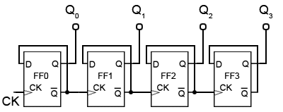
Fig. 5.6.1 Four-bit Asynchronous Up Counter
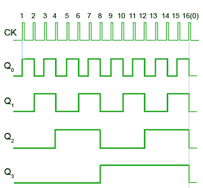
Fig. 5.6.2 Four-bit Asynchronous Up Counter Waveforms
Asynchronous Counters.
Counters, consisting of a number of flip-flops, count a stream of pulses applied to the counter’s CK input. The output is a binary value whose value is equal to the number of pulses received at the CK input.
Each output represents one bit of the output word, which, in 74 series counter ICs is usually 4 bits long, and the size of the output word depends on the number of flip-flops that make up the counter. The output lines of a 4-bit counter represent the values 20, 21, 22 and 23, or 1,2,4 and 8 respectively. They are normally shown in schematic diagrams in reverse order, with the least significant bit at the left, this is to enable the schematic diagram to show the circuit following the convention that signals flow from left to right, therefore in this case the CK input is at the left.
Four Bit Asynchronous Up Counter
Fig. 5.6.1 shows a 4 bit asynchronous up counter built from four positive edge triggered D type flip-flops connected in toggle mode. Clock pulses are fed into the CK input of FF0 whose output, Q0 provides the 20 output for FF1 after one CK pulse.
The rising edge of the Q output of each flip-flop triggers the CK input of the next flip-flop at half the frequency of the CK pulses applied to its input.
The Q outputs then represent a four-bit binary count with Q0 to Q3 representing 20 (1) to 23 (8) respectively.
Assuming that the four Q outputs are initially at 0000, the rising edge of the first CK pulse applied will cause the output Q0 to go to logic 1, and the next CK pulse will make Q0 output return to logic 0, and at the same time Q0 will go from 0 to 1.
As Q0 (and the CK input of FF1 goes high) this will now make Q1 high, indicating a value of 21 (210) on the Q outputs.
The next (third) CK pulse will cause Q0 to go to logic 1 again, so both Q0 and Q1 will now be high, making the 4-bit output 11002 (310 remembering that Q0 is the least significant bit).
The fourth CK pulse will make both Q0 and Q1 return to 0 and as Q1 will go high at this time, this will toggle FF2, making Q2 high and indicating 00102 (410) at the outputs.
Reading the output word from right to left, the Q outputs therefore continue to represent a binary number equalling the number of input pulses received at the CK input of FF0. As this is a four-stage counter the flip-flops will continue to toggle in sequence and the four Q outputs will output a sequence of binary values from 00002 to 11112 (0 to 1510) before the output returns to 00002 and begins to count up again as illustrated by the waveforms in Fig 5.6.2.
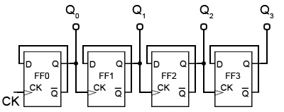
Fig. 5.6.3 Four-bit Asynchronous Down Counter
Four Bit Asynchronous Down Counter
To convert the up counter in Fig. 5.6.1 to count DOWN instead, is simply a matter of modifying the connections between the flip-flops. By taking both the output lines and the CK pulse for the next flip-flop in sequence from the Q output as shown in Fig. 5.6.3, a positive edge triggered counter will count down from 11112 to 00002.
Although both up and down counters can be built, using the asynchronous method for propagating the clock, they are not widely used as counters as they become unreliable at high clock speeds, or when a large number of flip-flops are connected together to give larger counts, due to the clock ripple effect.

Fig.5.6.4 Timing Diagram Detail Showing Clock Ripple
Clock Ripple
The effect of clock ripple in asynchronous counters is illustrated in Fig. 5.6.4, which is a magnified section (pulse 8) of Fig. 5.6.2.
Fig. 5.6.4 shows how the propagation delays created by the gates in each flip-flop (indicated by the blue vertical lines) add, over a number of flip-flops, to form a significant amount of delay between the time at which the output changes at the first flip flop (the least significant bit), and the last flip flop (the most significant bit).
As the Q0 to Q3 outputs each change at different times, a number of different output states occur as any particular clock pulse causes a new value to appear at the outputs.
At CK pulse 8 for example, the outputs Q0 to Q3 should change from 11102 (710) to 00012 (810), however what really happens (reading the vertical columns of 1s and 0s in Fig. 5.6.4) is that the outputs change, over a period of around 400 to 700ns, in the following sequence:
- 11102 = 710
- 01102 = 610
- 00102 = 410
- 00002 = 010
- 00012 = 810
At CK pulses other that pulse 8 of course, different sequences will occur, therefore there will be periods, as a change of value ripples through the chain of flip-flops, when unexpected values appear at the Q outputs for a very short time. However this can cause problems when a particular binary value is to be selected, as in the case of a decade counter, which must count from 00002 to 10012 (910) and then reset to 00002 on a count of 10102 (1010).
These short-lived logic values will also cause a series of very short spikes on the Q outputs, as the propagation delay of a single flip-flop is only about 100 to 150ns. These spikes are called ‘runt spikes’ and although they may not all reach to full logic 1 value every time, as well as possibly causing false counter triggering, they must also be considered as a possible cause of interference to other parts of the circuit.
Although this problem prevents the circuit being used as a reliable counter, it is still valuable as a simple and effective frequency divider, where a high frequency oscillator provides the input and each flip-flop in the chain divides the frequency by two.
Synchronous Counters
The synchronous counter provides a more reliable circuit for counting purposes, and for high-speed operation, as the clock pulses in this circuit are fed to every flip-flop in the chain at exactly the same time. Synchronous counters use JK flip-flops, as the programmable J and K inputs allow the toggling of individual flip-flops to be enabled or disabled at various stages of the count. Synchronous counters therefore eliminate the clock ripple problem, as the operation of the circuit is synchronised to the CK pulses, rather than flip-flop outputs.
Synchronous Up Counter

Fig.5.6.5 Synchronous Clock Connection
Fig. 5.6.5 shows how the clock pulses are applied in a synchronous counter. Notice that the CK input is applied to all the flip-flops in parallel. Therefore, as all the flip-flops receive a clock pulse at the same instant, some method must be used to prevent all the flip-flops changing state at the same time. This of course would result in the counter outputs simply toggling from all ones to all zeros, and back again with each clock pulse.
However, with JK flip-flops, when both J and K inputs are logic 1 the output toggles on each CK pulse, but when J and K are both at logic 0 no change takes place.
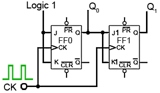
Fig. 5.6.6 The First Two Stages of a Synchronous Counter
Fig. 5.6.6 shows two stages of a synchronous counter. The binary output is taken from the Q outputs of the flip-flops. Note that on FF0 the J and K inputs are permanently wired to logic 1, so Q0 will change state (toggle) on each clock pulse. This provides the ‘ones’ count for the least significant bit.
On FF1 the J1 and K1 inputs are both connected to Q0 so that FF1 output will only be in toggle mode when Q0 is also at logic 1. As this only happens on alternate clock pulses, Q1 will only toggle on even numbered clock pulses giving a ‘twos’ count on the Q1 output.
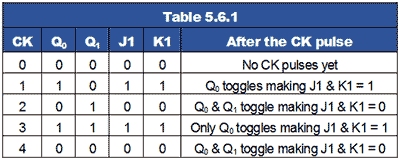
Table 5.6.1 shows this action, where it can be seen that Q1 toggles on the clock pulse only when J1 and K1 are high, giving a two bit binary count on the Q outputs, (where Q0 is the least significant bit).
In adding a third flip flop to the counter however, direct connection from J and K to the previous Q1 output would not give the correct count. Because Q1 is high at a count of 210 this would mean that FF2 would toggle on clock pulse three, as J2 and K2 would be high. Therefore clock pulse 3 would give a binary count of 1112 or 710 instead of 410.
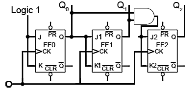
Fig. 5.6.7 Adding a Third Stage
To prevent this problem an AND gate is used, as shown in Fig. 5.6.7 to ensure that J2 and K2 are high only when both Q0 and Q1 are at logic 1 (i.e. at a count of three). Only when the outputs are in this state will the next clock pulse toggle Q2 to logic 1. The outputs Q0 and Q1 will of course return to logic 0 on this pulse, so giving a count of 0012 or 410 (with Q0 being the least significant bit).
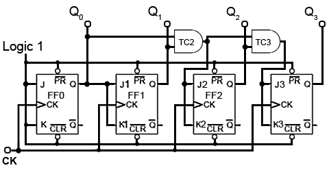
Fig. 5.6.8 shows the additional gating for a four stage synchronous counter. Here FF3 is put into toggle mode by making J3 and K3 logic 1, only when Q0 Q1 and Q2 are all at logic 1.
Q3 therefore will not toggle to its high state until the eighth clock pulse, and will remain high until the sixteenth clock pulse. After this pulse, all the Q outputs will return to zero.
Note that for this basic form of the synchronous counter to work, the PR and CLR inputs must also be all at logic 1, (their inactive state) as shown in Fig. 5.6.8.
Synchronous Down Counter
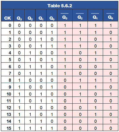
Converting the synchronous up counter to count down is simply a matter of reversing the count. If all of the ones and zeros in the 0 to 1510 sequence shown in Table 5.6.2 are complemented, (shown with a pink background) the sequence becomes 1510 to 0.
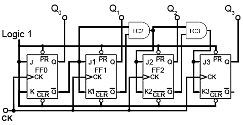
Down Counter Circuit
As every Q output on the JK flip-flops has its complement on Q, all that is needed to convert the up counter in Fig. 5.6.8 to the down counter shown in Fig 5.6.9 is to take the JK inputs for FF1 from the Q output of FF0 instead of the Q output. Gate TC2 now takes its inputs from the Q outputs of FF0 and FF1, and TC3 also takes its input from FF2 Q output.
Up/Down Counter
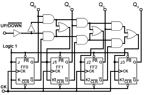
Fig. 5.6.10 illustrates how a single input, called (UP/DOWN) can be used to make a single counter count either up or down, depending on the logic state at the UP/DOWN input.
Each group of gates between successive flip-flops is in fact a modified data select circuit described in Combinational Logic Module 4.2, but in this version an AND/OR combination is used in preference to its DeMorgan equivalent NAND gate circuit. This is necessary to provide the correct logic state for the next data selector.
The Q and Q outputs of flip-flops FF0, FF1 and FF2 are connected to what are, in effect, the A and B data inputs of the data selectors. If the control input is at logic 1 then the CK pulse to the next flip-flop is fed from the Q output, making the counter an UP counter, but if the control input is 0 then CK pulses are fed from Q and the counter is a DOWN counter.
Synchronous BCD Up Counter
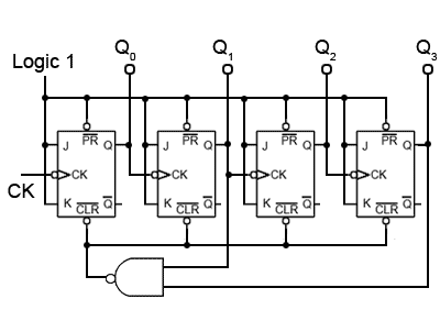
A typical use of the CLR inputs is illustrated in the BCD Up Counter in Fig 5.6.11. The counter outputs Q1 and Q3 are connected to the inputs of a NAND gate, the output of which is taken to the CLR inputs of all four flip-flops. When Q1 and Q3 are both at logic 1, the output terminal of the limit detection NAND gate (LD1) will become logic 0 and reset all the flip-flop outputs to logic 0.
Because the first time Q1 and Q3 are both at logic 1 during a 0 to 1510 count is at a count of ten (10102), this will cause the counter to count from 0 to 910 and then reset to 0, omitting 1010 to 1510.
The circuit is therefore a BCD8421 counter, an extremely useful device for driving numeric displays via a BCD to 7-segment decoder etc. However by re-designing the gating system to produce logic 0 at the CLR inputs for a different maximum value, any count other than 0 to 15 can be achieved.
If you already have a simulator such as Logisim installed on your computer, why not try designing an Octal up counter for example.
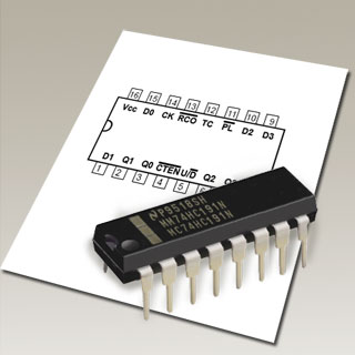
Fig. 5.6.12 Counter IC Inputs and Outputs
Counter IC Inputs and Outputs
Although synchronous counters can be, and are built from individual JK flip-flops, in many circuits they will be ether built into dedicated counter ICs, or into other large scale integrated circuits (LSICs).
For many applications the counters contained within ICs have extra inputs and outputs added to increase the counters versatility. The differences between many commercial counter ICs are basically the different input and output facilities offered. Some of which are described below. Notice that many of these inputs are active low; this derives from the fact that in earlier TTL devices any unconnected input would float up to logic 1 and hence become inactive. However leaving inputs un-connected is not good practice, especially CMOS inputs, which float between logic states, and could easily be activated to either valid logic state by random noise in the circuit, therefore ANY unused input should be permanently connected to its inactive logic state.
Enable Inputs
ENABLE (EN) inputs on counter ICs may have a number of different names, e.g. Chip Enable (CE), Count Enable (CTEN), Output Enable (ON) etc., each denoting the same or similar functions.
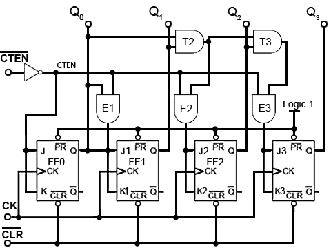
Count Enable (CTEN) for example, is a feature on counter integrated circuits, and in the synchronous counter illustrated in Fig 5.6.13, is an active low input. When it is set to logic 1, it will prevent the count from progressing, even in the presence of clock pulses, but the count will continue normally when CTEN is at logic 0.
A common way of disabling the counter, whilst retaining any current data on the Q outputs, is to inhibit the toggle action of the JK flip-flops whilst CTEN is inactive (logic 1), by making the JK inputs of all the flip-flops logic 0. However, as the logic states of the JK inputs of FF1, FF2 and FF3 depend on the state of the previous Q output, either directly or via gates T2 and T3, in order to preserve the output data, the Q outputs must be isolated from the JK inputs whenever CTEN is logic 1, but the Q outputs must connect to the JK inputs when CTEN is at logic 0 (the count enabled state).
This is achieved by using the extra (AND) enable gates, E1, E2 and E3, each of which have one of their inputs connected to CTEN (the inverse of CTEN). When the count is disabled, CTEN and therefore one of the inputs on each of , E1, E2 and E3 will be at logic 0, which will cause these enable gate outputs, and the flip-flop JK inputs to also be at logic 0, whatever logic states are present on the Q outputs, and also at the other enable gate inputs. Therefore whenever CTEN is at logic 1 the count is disabled.
When CTEN is at logic 0 however, CTEN will be logic 1 and E1, E2 and E3 will be enabled, causing whatever logic state is present on the Q outputs to be passed to the JK inputs. In this condition, when the next clock pulse is received at the CK input the flip-flops will toggle, following their normal sequence.
Asynchronous Parallel Load
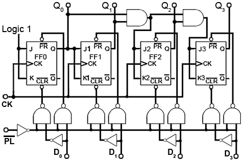
While common PR and CLR inputs can produce outputs of 0000 or 1111, a PARALLEL LOAD (PL) input will allow any value to be loaded into the counter. Using a separate DATA input for each flip-flop, and a small amount of extra logic, a logic 0 on the PL will load the counter with any pre-determined binary value before the start of, or during the count. A method of achieving asynchronous parallel loading on a synchronous counter is shown in Fig. 5.6.14.
Load Operation
The binary value to be loaded into the counter is applied to inputs D0 to D3 and a logic 0 pulse is applied to the PL input. This logic 0 is inverted and applied to one input of each of the eight NAND gates to enable them. If the value to be loaded into a particular flip-flop is logic 1, this makes the inputs of the right hand NAND gate 1,1 and due to the inverter between the pair of NAND gates for that particular input, the left hand NAND gate inputs will be 1,0.
The result of this is that logic 0 is applied to the flip-flop PR input and logic 1 is applied to the CLR input. This combination sets the Q output to logic 1, the same value that was applied to the D input. Similarly if a D input is at logic 0 the output of the left hand NAND gate of the pair will be Logic 0 and the right hand gate output will be logic 1, which will clear the Q output of the flip-flop. Because the PL input is common to each pair of load NAND gates, all four flip-flops are loaded simultaneously with the value, either 1 or 0 present at its particular D input.
Multiple Inputs and Outputs
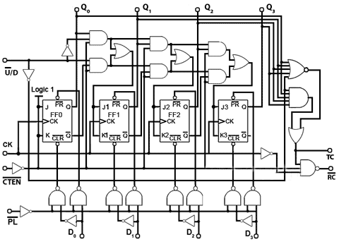
Modifications such as those described in this module make the basic synchronous counter much more versatile. Both TTL and CMOS synchronous counters are available in the 74 series of ICs containing usually 4-bit counters with these and other modifications for a wide variety of applications. Fig 5.6.15 shows how all the input functions described above, plus some important outputs such as Ripple Carry (RC) and Terminal Count (TC) can be combined to form a single synchronous counter IC.
A typical single synchronous IC such as the 74HC191 four-bit binary up/down counter also uses these input and output functions, which are designated on NXP versions (Fig. 5.6.16) as follows:
Inputs
• D0, D1, D2 and D3 (Load inputs) - A 4 bit binary number may be loaded into the counter via these inputs when the Parallel Load input PL is at logic 0.
• CE (Count Enable) - Allows the count to proceed when at 0. Stops count without resetting when at logic 1.
• U/D (Up/Down) - Counts up when 0, down when at logic 1.
• CP - Clock Pulse input.
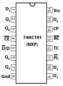
Fig. 5.6.16 74HC191 Pinout
Outputs
• Q0, Q1, Q2 and Q3 - Four bit binary output.
• TC (Terminal Count) - Also called MAX/MIN in some versions, gives a logic 1 pulse, equal in width to one full clock cycle, at each change over of the most significant bit (signifying that the count has overflowed beyond the end of an up or down count). TC can be used to detect the end of an up or down count, and as well as being available as an output, TC is used internally to generate the Ripple Carry output.
• RC (Ripple Carry) - Outputs a logic 0 pulse, equal in width to the low portion of the clock cycle at the end of a count, and when connected to the clock input of another 74HC191 IC it acts as a ‘carry’ to the next counter.
Cascading Synchronous Counters
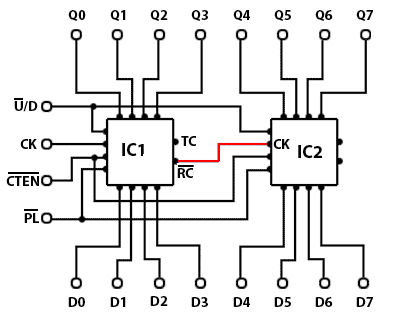
Connecting Synchronous counters in cascade, to obtain greater count ranges, is made simple in ICs such as the 74HC191 by using the ripple carry (RC) output of the IC counting the least significant 4 bits, to drive the clock input of the next most significant IC, as show in red in Fig. 5.6.17.
Although it may appear that either the TC or the RC outputs could drive the next clock input, the TC output is not intended for this purpose, as timing issues can occur.
Synchronous vs. Asynchronous Counters
Although synchronous counters have a great advantage over asynchronous or ripple counters in regard to reducing timing problems, there are situations where ripple counters have an advantage over synchronous counters.
When used at high speeds, only the first flip-flop in the ripple counter chain runs at the clock frequency. Each subsequent flip-flop runs at half the frequency of the previous one. In synchronous counters, with every stage operating at very high clock frequencies, stray capacitive coupling between the counter and other components and within the counter itself is more likely occur, so that in synchronous counters interference can be transferred between different stages of the counter, upsetting the count if adequate decoupling is not provided. This problem is reduced in ripple counters due to the lower frequencies in most of the stages.
Also, because the clock pulses applied to synchronous counters must charge, and discharge the input capacitance of every flip-flop simultaneously; synchronous counters having many flip-flops will cause large pulses of charge and discharge current in the clock driver circuits every time the clock changes logic state. This can also cause unwelcome spikes on the supply lines that could cause problems elsewhere in the digital circuitry. This is less of a problem with asynchronous counters, as the clock is only driving the first flip-flop in the counter chain.
Asynchronous counters are mostly used for frequency division applications and for generating time delays. In either of these applications the timing of individual outputs is not likely to cause a problem to external circuitry, and the fact that most of the stages in the counter run at much lower frequencies than the input clock, greatly reduces any problem of high frequency noise interference to surrounding components.
Counter ICs
synchronous (Ripple) Counters:
- 74HC390 - Dual decade ripple counter from NXP.
- 74HC393 - Dual 4-stage binary ripple counter from ON Semiconductor.
- 74HC4040 - 12-Stage binary ripple counter from Fairchild Semiconductor.
- 74HC93 - 4-Bit binary ripple counter from Texas Instruments.
- CD4060 - 14-Stage binary counter plus oscillator from ST Microelectronics.
- HEF4042B - 7-Stage binary ripple counter from NXP.
Synchronous Counters:
- 74HC160 - Pre-settable synchronous BCD counter with asynchronous reset from NXP.
- 74HC161 - 4-Bit synchronous BCD counter with asynchronous reset and synchronous load from Texas Instruments.
- 74HC163 - 4-Bit synchronous binary counter with asynchronous reset and synchronous load from Texas Instruments.
- 74HC191 - 4-bit synchronous binary up/down counter with asynchronous reset and load from NXP.
- 74HC192 - 4-Bit synchronous BCD counter with asynchronous reset and load from Texas Instruments.
- 74HC193 - 4-Bit synchronous binary counter with asynchronous reset and load from Texas Instruments.
- CD4017/4022B - 4-Stage synchronous counters with Decade (1 of 10) or Octal (1 of 8) outputs from Texas Instrumentss.


