
Google Ads
Module 2.5
Light Emitting Diodes
- After studying this section, you should be able to:
- • Describe typical construction methods for LEDs.
- • Understand the operation of LEDs.
- • Coloured LEDs
- • Methods for producing White LEDs.
- • Current limiting for LEDs.
- • Multiple LED arrays.
- • Describe methods for testing lEDs.
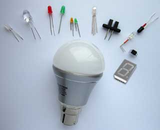
Figure 2.5.1. LEDs
Light Emitting Diodes (LEDs)

Fig. 2.5.1 shows a range of LEDs illustrating some of the wide range of styles and sizes of LEDs available. Colours range across the visible light spectrum from deep red to ultra violet as well as shades of white. Additionally infra-red LEDs are used in many sensors and remote control applications.
From left to right the LEDs in Fig. 2.5.1 are 5mm warm white, 10mm ultra high brightness blue, standard 5mm red & green, miniature yellow & green, tri-colour (red/green/blue), infra-red opto-coupler, infra-red transmitter/receiver, and an infra-red opto-isolator. Below is a 230V 8W 230 lumens warm white LED light bulb and a 7-segment display.
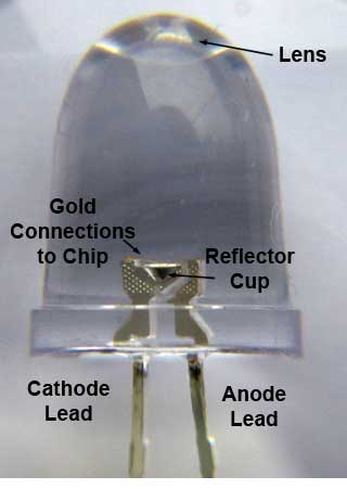
Figure 2.5.2. LED Construction
(Side View)
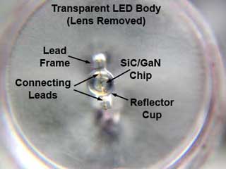
Figure 2.5.3. LED Construction
(Top View)
How LEDs Work
In semiconductor diodes whenever an electron recombines with a hole, energy is released for a brief moment in the form of a photon. Ordinary silicon diodes are not suitable for light emission as in the silicon PN junction, the photons produced are mostly converted to heat within the silicon, and only a very small amount of light can escape the diode structure. This light also has a wavelength limited to the infrared region. For several decades, light emitting diodes have used materials such as gallium arsenide(GaAs), gallium arsenide phosphide(GaAsP), or gallium phosphide(GaP), which make PN junctions more efficient at producing light. These compound materials also have carefully controlled amounts of indium(In) or aluminium(Al) added and can be doped with other elements such as magnesium(Mg). This enables the production of the more common LED colours of red, orange, yellow and green. Blue LEDs are now also made possible by using silicon carbide(SiC) and gallium nitride(GaN). The colour and brightness of an LED depends on the combination of materials used and the energy gaps of the P and N materials on either side of the junction.
The energy gap (the amount of energy needed to move an electron from the valence band of an atom into its conductance band) of the semiconductor material on ether side of the PN junction is different in different semiconductor materials, and as current flows through the LED, electrons in the higher energy band recombine across the junction layer with holes in the lower energy band. In doing so the electrons lose some energy and it is this energy that is emitted by the LED as light.
The more energy the electrons lose in this process, the higher the frequency (and the shorter the wavelength) of the light produced. Fig. 2.5.4 illustrates the different combinations of semiconductor materials used to produce light of different colours.
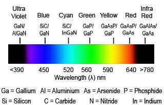
Figure 2.5.4. LED Colours
Generally the light resulting from each electron/hole recombination is very directional and short lived, but the millions of recombinations happening when the LED is forward biased produce light continuously. Because the light is emitted in narrow beams at many angles, to make this scattered light more useful, the LED chip is mounted at the focus point of a reflector cup, which focuses the light emitted by the chip into a cone shaped beam.
The clear plastic body of the LED also contains a lens to better focus the light into a beam. Some LEDs use a coloured plastic body, generally red, yellow or green, but the body colour is only to identify the colour of the LED in its unlit state and makes little or no difference to the colour emitted by the LED chip. The range of different colours available from LEDs is illustrated in Fig. 2.5.4
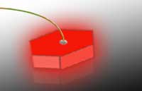
Figure 2.5.5. Hexagonal
LED Chip
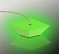
Figure 2.5.6. Pyramid
LED Chip
Maximising Light Output
A problem with traditional LEDs however, is that the amount of light leaving the LED chip might only be around 20% of the actual photons generated within the chip. The reason for this is that whilst a beam of light (a photon) approaching the chip wall at an angle perpendicular to the surface, passes easily from the chip into the surrounding medium (e.g. the transparent plastic of the LED body), light approaching the chip surface at other angles is deflected by refraction as it meets interface between the chip and the surrounding material. This is due to a change in the speed of light between the different materials. When a beam of light arrives at the interface of of the chip and the surrounding plastic at an angle greater than the ‘critical angle’ for the two materials concerned, it is reflected back into the chip, where the photon energy is dissipated as heat.
To overcome this problem and increase the light output from the chip as well as reducing the heat produced during operation, a number of manufacturers are producing LED chips that do not have the regular rectangular shape, by cutting the individual chips into polygons instead of rectangles as shown in Fig. 2.5.5. Another approach is to cut the sides of a rectangular chip at an angle, forming a partial pyramid as shown in Fig. 2.5.6. These techniques increase the chances of internally reflected photons arriving at another chip surface at an angle that allows them to pass through the surface, so increasing light output.
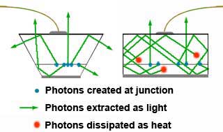
Figure 2.5.7. Internal Reflection
By replacing sides that are at right angles to each other with sides at various angles, the chance of a photon emitted from the LED junction at any random angle arriving at the boundary of the chip at an angle that allows it to leave the chip rather than being reflected internally is increased, as illustrated in Fig. 2.5.7. In this way light extraction is increased and internal heat generation is decreased, allowing for the manufacture of more efficient LEDs.
White LEDs
Three main types of white LEDs are available, the first is actually a blue LED in which the emitted light activates a yellow phosphor coating to give the effect of white light, however the white light produced by this blue/yellow combination, unlike sunlight does not have an even energy spread over the whole light spectrum so is not particularly suitable for accurate colour matching applications.
A second type of white LED actually comprises three LEDs (red green and blue) in a single package. This type gives a more even light spectrum and some versions allow for each of the three individual colours to be independently varied. This is an important feature because one problem with LEDs is that their output can vary with temperature, and red, green and blue LEDs do not all vary by the same amount for a given temperature change. These LEDs therefore require more complex (temperature sensitive) control circuits if a pure white is to be maintained, however this system also gives the opportunity to create variable multi-colour lighting.
A third approach is to use an ultra-violet LED to stimulate a mixture of phosphors designed to give a white light covering the full visible spectrum without the ‘gaps’ left by the blue/yellow system and, because only one (invisible) LED is involved, overcoming the temperature stability issues of the three LED system.
Figure 2.5.8. LED Characteristics Compared
LED Colour
LEDs currently cover a wide range of colours, light outputs and power requirements and are generally many times more reliable and use much less power than competitive incandescent or fluorescent alternatives.
To make a LED glow it is necessary to forward bias the diode sufficiently to pass an appropriate amount of current, generally the shorter the wavelength of the light produced, the higher the voltage required for forward bias, and typical forward bias voltages vary from 1.5 to 1.7V for infrared LEDs to 3.3V or more for blue and ultraviolet. The commoner red yellow and green versions require around 2V forward bias and white LEDs about 3.6V.
Fig. 2.5.8 shows typical characteristics for various colours of LED. Notice the considerable difference between the forward voltage (VF) for blue types and red to green types. Blue LEDs also typically have a greater reverse leakage current (IREV) than other LEDs but the safe limit for most LEDs is considered to be around -5V, a VERY LOW value compared with silicon diodes, which may have reverse breakdown voltages measured in tens or hundreds of volts. Therefore LEDs are more easily damaged by relatively small values of either excess forward current, or reverse voltage compared to ordinary silicon diodes, so to take advantage of the LED´s excellent reliability, care must be taken to ensure that any LED operates within its safe operating area.
Connecting LEDs
Figure 2.5.9. LED Current Limiting Resistor
To ensure that the forward current through the LED is correct for the type of LED used, it is best to consult the relevant data sheet. If the appropriate data sheet is not available good and comprehensive data on LED's is available on the web sites of specialist manufacturers such as Kingbright.
Having found an appropriate figure for forward current, a current limiting resistor (RLIM) such as that shown in Fig. 2.5.9 can easily be calculated by subtracting the appropriate forward voltage for the LED (VF) from the supply voltage (VS) to give the required voltage across the resistor (VR), and then dividing VR by the required forward current (IF). It will be unlikely that the result of your calculation will be a preferred value of resistor, in this case choose the next higher preferred value.

As resistors are available in a range of standard power ratings, e.g 0.25W 0.5W etc, the power dissipation (wattage) required for RLIM should be the next higher power rating available, greater than the power calculated by multiplying the chosen preferred value of RLIM by the square of the diode's forward current. RLIM x IF2.
LED Arrays
Figure 2.5.10. Series-Parallel LED Array
LEDs are often used in multiple arrays as shown in Fig. 2.5.10 and a typical method of connection is to connect a number of LEDs in series, fed via a single limiting resistor from a higher voltage supply(VS) than would be required for a single LED. The current through each series connected LED is identical to that required for a single LED but the the voltage across the four LEDs in Fig. 2.5.10 is four times that required for a single LED (i.e. VF1 + VF2 + VF3 + VF4).
A number of identical series groups may be connected in parallel as shown in Fig.2.5.10. There are several advantages to this method of connection:
1. The supply voltage does not need to be as high as if many LEDs were connected in series, making this method more suitable for battery supplies.
2. A smaller number of limiting resistors are needed, only one per series group rather than one per LED, compared to an all parallel connection.
3. The effect of a faulty LED on the total light output is reduced. If one LED develops a short circuit only that LED will fail to light, however the remaining LEDs in the four diode series group will experience a 25% increase in current. With more LEDs in the group this effect would be reduced. If any one of the diodes develops an open circuit, then only the four LEDs in the affected series group will fail to light, the rest of the LEDs will work normally.
D1 might typically be included in a battery powered circuit to prevent damage from any accidental reverse polarity battery connection.
Testing LEDs
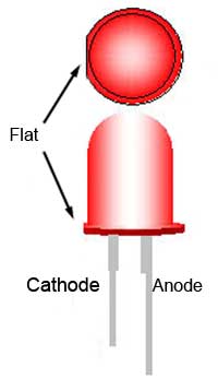
Figure 2.5.11. LED Polarity
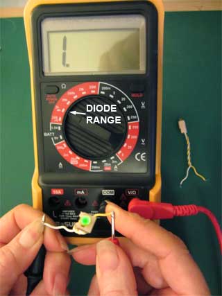
Figure 2.5.12. Testing a LED
Correct polarity must be observed when connecting LEDs and unfortunately the anode and cathode connections of LEDs are not always readily apparent. Fig. 2.5.11 illustrates the two ways that polarity is indicated on standard 5mm LEDs but these depend on the connecting leads not being shortened (as they often are) or being able to see the slight ‘flat’ near the cathode lead, which is not always easy. With larger clear LEDs it may be possible to determine the cathode of the device by looking at the internal structure of the LED. In this case the larger of the two internal lead structures is the cathode (See Fig 2.5.2).
As LEDs are available in so many shapes and sizes it is often not possible to determine which is the anode and which the cathode connections visibly. To overcome this problem there are a number of testing devices on the market varying in price from less than $10 to around $160 but simple (and cheaper) tests can be carried out with a basic multi meter switched to the diode range that will not only reveal the polarity of the diode but also show whether the LED is faulty or not. In Fig. 2.5.12 a typical problem is shown where a miniature green LED that has been mounted in a wired holder, needs testing.
Simply connecting the multi meter leads is usually sufficient to make the LED glow (often weakly) when the red lead is connected to the anode and black to cathode. Reversing the leads will not make the diode glow, so revealing in this case, that the yellow lead on the LED holder, is connected to the anode. Notice however that the meter is still showing 1 on its display indicating that the LED is open circuit when it clearly is not because its working!
Some LEDs will fail to light in this test, no matter which way round the meter leads are connected, suggesting an open circuit diode but at the same time will give an infinity (1 on the display) reading in one direction, indicating a very high resistance, and a reading of perhaps several hundred or perhaps slightly more than 1KΩ in the other direction, indicating a good LED. The results depend on both the characteristics of the diode and on the meter used, as well as on the condition of the meter battery. If all this seems confusing, just assume that when testing an LED out of circuit:
If either testing an out of circuit LED for a glow, or for different resistance readings as described above indicates a good LED, then it very probably is a good LED.
If both tests suggest a faulty LED then the LED is very probably faulty.