Module 8.0
Filters and Waveshaping
- Module 8 Introduction
- Recognise passive filters with reference to their response curves.
- • High pass.
- • Low pass.
- • Band stop.
- Section 8.1 Passive Filters.
- Recognise typical filter circuits.
- • RC, LC and LR filters.
- • Uses for passive filters
- Recognise packaged filters.
- • Ceramic filters.
- • SAW filter.
- • Three−wire encapsulated filters.
- Section 8.2 How Filters Work.
- How passive filters achieve frequency selective attenuation and phase change with reference to phasor diagrams.
- • High pass filters.
- • Low pass filters.
- Section 8.3 Bode Plots.
- Bode Plots.
- The use of Bode plots to describe:
- • Attenuation.
- • Phase Change
- Section 8.4 Differentiators
- The use of RC filters in waveshaping on non−sinusoidal waveforms.
- • Differentiation.
- Section 8.5 Integrators.
- The use of RC filters in waveshaping on non−sinusoidal waveforms.
- • Integration.
- Section 8.6 Filter Quiz.
- • Filter Quiz.
Passive Filters
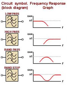
Passive filters are circuit sub units often consisting of only two or three components, which reduce (ATTENUATE) the amplitude of signals, They are designed to be frequency selective so that they can reduce the signal amplitude at some frequencies, but do not affect signals at others. Filter circuits are given different names, depending on which frequencies they affect. Fig 8.0.1 shows the circuit symbols used in block (system) diagrams for some filters, and beside them a diagram representing the frequency response of that filter. The block diagrams indicate the frequency that is attenuated by showing three sine waves with one or two crossed out, the vertical position of the wave indicating high medium or low frequencies.

Fig. 8.0.1 Filters.
To indicate the effect a filter has on wave amplitude at different frequencies, a frequency response graph may be used. This graph plots gain (on the vertical axis) against frequency, and shows the relative output levels over a band of different frequencies.
Passive filters do not contain any "active components", such as transistors, capable of increasing the signal level of the filter output. They use only what are called "passive components" such as resistors, capacitors, and inductors. This means that, in simple capacitor-resistor (CR) filters, the signal amplitude at a filter output cannot be larger than the signal at the input. For this reason the maximum gain on any of the frequency response graphs is shown as slightly less than 1.
The main difference between passive filters and active filters (apart from the active filter´s ability to amplify signals) is that active filters can produce much steeper cut off slopes. However, passive filters do not require any external power supply and are adequate for a great many uses.


