Google Ads
Module 2
Class A Amplifier Design
- Section 2.0 Introduction to Amplifier Design.
- Section 2.1 DC Conditions.
- • Design a BJT class A common emitter audio amplifier.
- Section 2.2 AC Conditions.
- • Calculate suitable values for AC components.
- • Build a prototype amplifier on Breadboard.
- Section 2.3 Testing the Amplifier.
- • Test the amplifier for Gain, Bandwidth, Input and Output Impedance.
- Section 2.4 Improving the Amplifier.
- • Carry out tests and modifications, and apply Negative Feedback to achieve specified performance criteria.
- Section 2.5 Multi-stage Amplifiers.
- • Describe methods for inter-stage coupling in multi-stage amplifiers:
- Section 2.6 Amplifier Design Quiz.
- • Test your knowledge & understanding of basic amplifier design.
Basic design process.

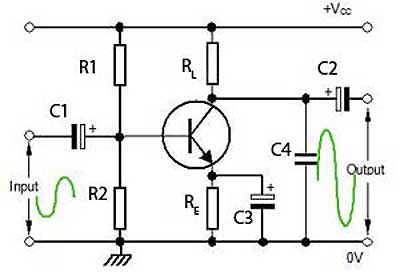
Fig. 2.0.1. Common Emitter Amplifier
Fig. 2.0.1 shows a class A common emitter amplifier, but without its component values. This module shows how to simply calculate the values needed to make a working amplifier that has correct class A bias as described in Amplifier Module 1.2 and so produce an undistorted and amplified output. Building and testing an amplifier is a good way learn how and why an amplifier works.
How will you know that your calculations are correct? The best way is to build your design and test it. Follow the guidelines in this section and download the accompanying pdf documents, so you can design, build and test a working amplifier.
Although amplifier design can be a complex process, this simple exercise takes some short cuts, because it is more concerned with learning about how an amplifier works, rather than designing a complete new hi-fi system.
Amplifier Design Project
Sections 2.1 to 2.4 of this module are a practical project to design a single stage class A common emitter amplifier. Use information from other sections modules in learnabout-electronics (just click the links where needed) to help you calculate the component values needed for a working amplifier. The only maths involved will be some Ohms law and some capacitive reactance calculations.
The Amplifier Design Record
Download and print out the Amplifier Design Record, which can be used in conjunction with sections 2.1 to 2.4 of this module so you will have a complete record of how to design, build and test an amplifier. It contains all the formulae needed to calculate the correct DC and AC conditions for the amplifier, and once the Amplifier Design is complete, the prototype circuit can be easily built on breadboard (Proto board). The project also shows you how to test an amplifier for performance using a multimeter and oscilloscope.
The project is split into four sections so that it can be checked for errors as the design progresses. By splitting the design task in this way, there is far less chance of going wrong.
Carefully follow the design sequence instructions on line in sections 2.1 to 2.4 of this module, and record the results of your calculations and tests on the Amplifier Design Record sheets to design and build a working class A common emitter amplifier. This is a great way to understanding how an amplifier works.


