Google Ads
Module 4.1
Resistors in DC Circuits
- After studying this section, you should be able to describe:
- • Transient events in DC circuits.
- • The difference between Ideal and practical circuits
- • Transient voltage and current relationships in a simple resistive circuit
Transient Events
In AC circuits, voltage and current conditions are continually changing. We therefore need to include the effects of time and transient (passing) events on circuit conditions. A transient event is something that happens over a period of time, such as a switch opening or closing.

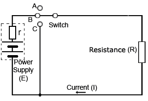
Fig 4.1.1 An Ideal Circuit
An Ideal Electrical Circuit in a Practical World
A theoretical or "ideal" DC circuit such as illustrated (right) contains only resistance. Every practical (real) circuit however, contains at least some capacitance and some inductance as well as resistance. Any circuit must contain metal conductors that will have some inductance. Also components or wires that are near others, with an insulating gap (air and/or plastic) between them, must effectively be capacitors. Therefore a purely resistive circuit only exists in theory. A circuit such as that in Fig. 4.1.1 can have one property, such as resistance much greater than the capacitance or the inductance naturally present, so these can be ignored for theoretical purposes, and the circuit considered as having only resistance. To indicate this, such a circuit is called an "ideal circuit". That is, one that contains only one pure property, in this case resistance.
Transient Conditions in a Restive Circuit
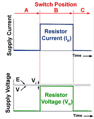
The transient operation of the circuit Fig.4.1.1, which happens during during switch operation, is shown in Fig. 4.1.2.
At first no current is flowing, but as the switch closes on contact B, the amount of current flowing will instantly rise to a maximum level. This will make the current(I) equal to the battery voltage (V) divided by the resistance (R). That is;
I=V/R
Which is an expression of Ohms law that can be used to calculate the value of current at any time, given the other two values.
Suppose V=10V and R=5Ω
This gives I=10/5 = 2Amperes.
And if R is increased to 10Ω while V remains the same,
Then I=10/10 = 1Ampere.
Increasing the resistance has reduced current flow.
Also, if the supply voltage is increased, while the resistance remains the same, the current increases.
Fig. 4.1.2, shows what happens to the voltage and current whilst the switch is closed, and then opened again. Both current and voltage rise immediately to a steady value as the switch is closed, then fall immediately to zero when the switch is opened.
The voltage across the resistor (VR) whilst the switch remains closed is given by
VR = I x R

Fig 4.1.2 What happens in the circuit.
What is the difference between E and V for voltage?
E (the e.m.f or electromotive force)is the term used to indicate the electrical potential that drives current around the circuit. Voltage (V) is the term used to indicate the difference in electrical potential between any two points in a circuit. This may be the voltage difference between the two ends of a resistor, in which case it would be called VR or the difference in potential between the two supply terminals, which may be called the supply voltage or VS. In a practical circuit however, it is possible for E and VS to be slightly different. This is because any power supply, such as a battery, will have some internal resistance, due to the materials used in the construction of the battery. This resistance designated (r), will usually be very small, although as a battery discharges it will increase in value, making the difference between the emf(E) and the voltage across the battery terminals (V) larger. Because this resistance will be in series with the circuit resistance R, this can make E and VR slightly different. Therefore to be totally accurate, E and V should be shown as separate quantities, which would modify the formula for current to I = E/(R+r)
The formula for VR remains VR = IR but the current (I) in the calculation would be slightly less because of the effect of r in the formula for current.
The resistance R can be calculated by R = VR /I
Whether the difference due to the supply resistance (r) is important or not depends on the required accuracy of any measurements. For example in a circuit with very low resistance and high current it may be significant, such as the voltage drop noticeable on an automobile battery when supplying the starter motor. Alternatively, if the circuit under consideration has a high resistance, drawing only a small supply current, the very small internal resistance of the supply will usually have no noticeable effect on circuit conditions. In many cases where measurements are being taken in electronic circuits, the fact of introducing additional current paths due to the connection of test equipment may easily alter the circuit conditions more than the effect of the supply resistance(r).


