Google Ads
Module 4.4
Inductance and Resistance in a DC circuit.
- After studying this section, you should be able to describe:
- • Transient events in DC circuits.
- • Transient voltage and current relationships in a simple LR circuit.

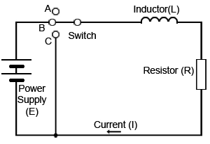
Fig. 4.4.1 The LR Circuit
In a circuit which contains inductance (L), as well as resistance (R), such as the one shown in Fig. 4.4.1, when the switch is closed the current does not rise immediately to its steady state value but rises in EXPONENTIAL fashion. This is due to the fact that a BACK EMF is created by the change in current flow through the inductor. This back EMF has an amplitude which is proportional to the RATE OF CHANGE of current (the faster the rate of change, the greater the back EMF) and a polarity which opposes the change in current in the inductor that caused it initially.
The back EMF is produced because the changing current in the inductor causes a changing magnetic field around it and the changing magnetic field causes, in turn, an EMF to be induced back into the inductor. This process is called SELF INDUCTION.
Current Through an Inductor

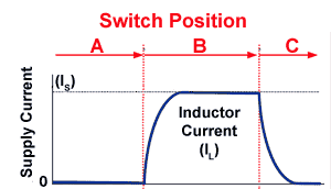
Fig. 4.4.2 Current Through an Inductor
Because the back EMF opposes the rapid change in current taking place in the inductor, the rate of change of current is reduced and what would be a vertical line on the graph (Fig. 4.4.2) becomes a slope. The rate of change of current through the inductor is now less, so a smaller back EMF is produced. This allows the current to increase further. The relationship between the changing current and back EMF produces a curve which always follows a mathematical law to produce a particular shape of curve i.e. an exponential curve. When the switch is opened, the current decays in a similar exponential manner towards zero.
Voltage Across an Inductor

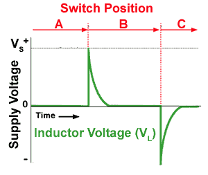
Fig. 4.4.3 Voltage Across an Inductor
Looking at Fig. 4.4.3 which shows the voltage (VL) across the inductor (L) we can see that at switch on, the voltage immediately rises to a maximum value. This is because a voltage is being applied to the circuit and little or no current is flowing because L is effectively (for a very short time) a very high resistance due to the back EMF effect caused by the rapidly changing (expanding) magnetic field around the inductor inducing a voltage (a back EMF) back into the inductor, which is in opposite polarity to the applied voltage from the supply, and so initially opposes the increase in current through the inductor. Because of this opposition caused by the back EMF it appears initially that the inductor has a very high resistance. and so the full supply voltage is developed across the inductor. As current through L begins to build however, the rate of change of the magnetic field reduces, the oppostion due to the back EMF reduces and the apparent 'resistance' of the inductor falls to a low value (the real resistance of the wire coil) and the voltage VL decreases until a point is reached where the whole of the battery voltage is being developed across the resistor R; the voltage or potential difference (pd) across L is practically zero and energy is now stored in the magnetic field around the inductor.
When the current is switched off the magnetic field is now collapses instead of growing as it did at switch on. This collapsing magnetic field now returns its energy into the inductor coil and induces a voltage (a back EMF) into the inductor, but because the change in magnetic field strenth is in the opposite direction to the expanding field at switch on, the induced voltage is now in the opposite polarity, as shown in Fig. 4.4.3. The induced back EMF now opposes the reduction in current cause by switch off, slowing down the decay of current as can be seen in Fig. 4.4.2.
The rapid collapse of the magnetic field as the switch opens can cause very large voltage spikes, because the amount of voltage induced is dependent on the rate of change of the magenetic field. The high voltages produced can lead to arcing at the switch contacts, as the voltage jumps the gap between the contacts. These large voltage spikes can also damage other components in a circuit, especially semiconductors, so care must be taken in the design of circuits containing inductors, or driving inductive loads, to prevent these spikes. In some circuits however, where high voltages are required, this effect can also be used to advantage, by applying a square wave to an inductor. The very large voltage spikes produced can then be rectified by special high voltage diodes to produce DC voltages of thousands of volts.


