Module 3.6
Transistor Connections
- After studying this section, you should be able to:
- Recognise basic transistor amplifier connection modes.
- • Common emitter.
- • Common collector.
- • Common base.
- Describe the basic parameters of each amplifier mode.
- • Voltage gain.
- • Current gain.
- • Input & output impedances.
How a transistor is connected to make an amplifier.

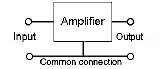
Fig. 3.6.1 Amplifier Connections.

Because an amplifier must have two input and two output terminals, a transistor used as an amplifier must have one of its three terminals common to both input and output as shown in Fig 3.6.1. The choice of which terminal is used as the common connection has a marked effect on the performance of the amplifier.
A transistor connected in the three modes illustrated in Figs. 3.6.2 to 3.6.4 would show quite different characteristic curves for each mode. These differences can be exploited by the circuit designer to give an amplifier with characteristics that are most suited a particular purpose. Note that the diagrams are shown here reduced to their most basic form and are not intended to be practical circuits.
In a transistor amplifier circuit, such as those shown in Figs. 3.6.2 to 3.6.4, the +V supply line and the 0V line can be considered as the same point, as far as any AC signal is concerned. This is because, although there is obviously a voltage (the supply voltage) between these two points, the DC supply is always de-coupled by a large capacitor (e.g. the reservoir capacitor in the power supply) so there can be no AC voltage difference between +V and 0V rails.

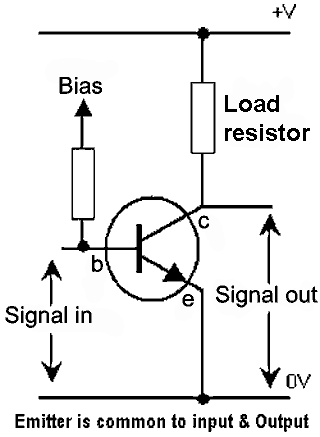
Fig. 3.6.2 Common Emitter Mode.
Common Emitter Mode
The most common function of a transistor is to be used in COMMON EMITTER mode. In this method of connection small changes in base/emitter current cause large changes in collector/emitter current. Therefore the circuit is that of a CURRENT amplifier. To give VOLTAGE amplification, a load resistor (or an impedance such as a tuned circuit) must be connected in the collector circuit, so that a change in collector current causes a change in the voltage developed across the load resistor. The value of the load resistor will affect the VOLTAGE GAIN of the amplifier. This is because the larger the load resistor, the larger the change in voltage that will be caused by a given change in collector current. Notice that because of this method of connection the output waveform will be in anti-phase to the input waveform. This is because an increase in base/emitter voltage will cause an increase in base current. This will in turn cause an increase in collector current, but as collector current increases, the voltage drop across the load resistor increases and as the voltage on the top end of the load resistor (the supply voltage) will not change, the voltage on the bottom end must decrease. Therefore an increase in base/emitter voltage causes a decrease in collector/emitter voltage.
Common Emitter Parameters
Voltage Gain: High (about 100).
Current Gain: High (about 50 to 800).
Input Impedance: Medium (about 3kΩ to 5kΩ).
Output Impedance: Medium (Appoximately the load resistor value).

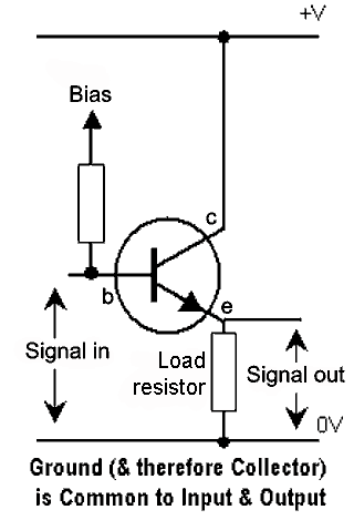
Fig. 3.6.3 Common Collector Mode.
Common Collector Mode
Fig. 3.6.3 illustrates the COMMON COLLECTOR mode; also called the emitter follower mode as in this circuit the output waveform at the emitter is not inverted and so ‘follows’ the input waveform at the base. This method of connection is often used as a BUFFER AMPLIFIER for such jobs as matching impedances between two other circuits. This is because this mode gives the amplifier a high input impedance and a low output impedance. The voltage gain in this mode is slightly less than unity (x 1), but high current gain (called hfc in common collector mode) is available. Another use for this mode of connection is a CURRENT AMPLIFIER, often used for output circuits that have to drive high current AC devices such as loudspeakers or DC devices such as motors etc.
Common Collector Parameters
Voltage Gain: Slightly less than unity (1).
Current Gain: High (about 50 to 800)
Input Impedance: High (Several kΩ)
Output Impedance: Low (A few ohms)

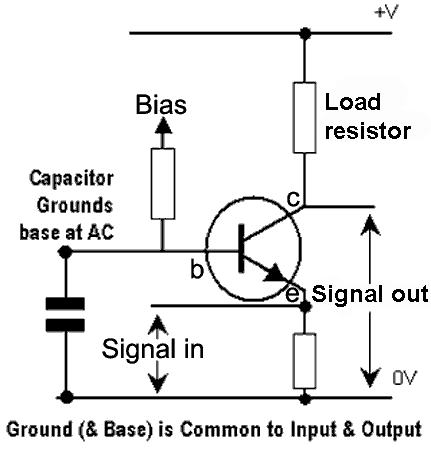
Fig. 3.6.4 Common Base Mode.
Common Base Mode
COMMON BASE MODE is usually used for VHF and UHF amplifiers where, although the voltage gain is not high, there is little chance of the output signal being fed back into the input circuit (which can be a problem at these frequencies). Because the base of the transistor is connected to ground in this mode, it forms an effective grounded (earthed) screen between output and input. As the collector current in this mode will be the emitter current minus the base current, the current gain (hfb in common base mode) is less than unity (<1).
Common Base Parameters
Voltage Gain: Medium (about 10 to 50).
Current Gain: Less than unity (<1)
Input Impedance: Low (about 50Ω)
Output Impedance: High (about 1MΩ)


