
Google Ads
Module 6.1
Silicon Controlled Rectifiers (SCRs) in DC Circuits
- After studying this section, you should be able to:
- Understand SCR operation in DC circuits:
- The SCR as a DC switch.
- The SCR as a Crowbar safety device.

Fig. 6.1.1 DC Control Using a Thyristor
DC Power Switching
Thyristors can be used to control either AC or DC loads and can be used to switch low voltage low current devices as well as very large currents at mains (line) voltages. A simple example of a thyristor controlling a DC load, such as a small DC motor is illustrated in Fig 6.1.1. The motor here is connected to a 12V DC supply via a BT151 thyristor, but will not run until the thyristor is made to conduct. This is achieved by momentarily closing the 'start' switch, which provides a pulse of current to the gate terminal of the thyristor. The motor now runs as the thyristor switches on and its resistance is now very low.
When the start switch returns to its normally open state, there is no longer any gate current but the thyristor continues to conduct, and in a DC circuit, current will continue to flow and the motor continues to run. Any further operations of the start switch now have no effect. The thyristor will only switch off if current flow reduces to a value below the thyristor's holding current threshold.
This is achieved by shorting out the thyristor by momentarily closing the 'stop' switch. The circuit current now flows through the stop switch rather than through the thyristor, which instantly turns off, as the SCR current is now reduced to less than the holding current value. Stopping the motor could also be achieved by using a normally closed switch in series with the thyristor, which when pressed, would also temporarily prevent current flow through the thyristor long enough for the thyristor to turn off.
Although this simple circuit works, as can be seen in the video accompanying Fig. 6.1.1 it is not difficult to imagine simpler ways of switching a small motor on and off. However the principle is useful in situations such as using a computer to control a DC motor. The small current produced by the computer's output is used to trigger a thyristor (usually via an opto coupled device to provide electrical isolation). The thyristor can then supply the motor or other device with whatever higher value of current is required. The use of a thyristor could, with some appropriate extra circuitry, also allow for remote switching of a circuit or device, triggered for example by a radio signal.
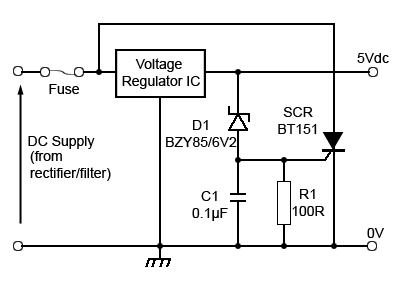
Fig. 6.1.2 Crowbar Over Voltage Protection
SCR Crowbar Circuits
Another DC operation using thyristors is the 'Crowbar' circuit, used as an over voltage protection device. The circuit is called a crowbar as its action is about as subtle as a swift blow with a crowbar. Such circuits may often be found preventing power supply circuits from outputting a higher than normal voltage under fault conditions.
The basic idea is that if, for example a fault in a DC power supply line causes the output to rise above its specified voltage value, this 'over voltage' is sensed and causes a normally non conducting SCR connected between the power supply output and ground to switch on very rapidly. This can have different protective actions, the simplest of which, as illustrated in Fig. 6.1.2 is to blow a fuse and so switch off the power completely, requiring the attention of a service technician to get the circuit working again. This is often chosen as the safest option as the cause of the original over voltage should be examined and eliminated before the circuit is allowed to work again.
In Fig. 6.1.2 the output of a regulated 5V DC supply is sensed by D1, a 6.2V Zener diode, the anode of which is held at a voltage close to 0V by R1. This 100Ω resistor ensures that if the 5V supply line rises above its specified limit, sufficient current flows through the Zener diode to provide enough current at the SCR gate to switch on the SCR. Care must also be taken to ensure that the SCR is not triggered accidentally by any fast voltage spikes appearing on the 5V line, due for example to other switching devices in the circuit being supplied. C1 is therefore connected between the gate and cathode of the SCR to reduce the amplitude of any very short interference pulses, provided they do not exist long enough to charge C1 to a high enough level to trigger the SCR.
The reason for using a thyristor to blow the fuse is that fuses do not blow immediately, they operate by blowing when excessive current flows for long enough so that the fusible element heats up and melts. This may take long enough for the excessive voltage to have already destroyed a number of semiconductor components. The thyristor however has a very fast switch on time (about 2µs for the BT151) so that during the short time between the over voltage occurring and the fuse blowing, the entire power supply output current will be flowing through the thyristor, rather than through the circuit being supplied.
Although circuits similar to Fig. 6.1.2 are widely used, relying on fuses to protect complex low voltage semiconductor circuits may not provide suitable protection. However an improved circuit that can prevent over voltage situations without blowing fuses, and which depends only on the almost instant action of semiconductors is described in our Power Supplies Module 2.2 on Series Voltage Regulators.