
Google Ads
Module 6.5
Thyristor Protection
- After studying this section, you should be able to:
- Recognise over voltage & over current conditions in SCRs:
- • High voltage spikes.
- • Voltage surges.
- • Causes of high current.
- Identify typical components for preventing over voltage and over current.
- Understand potential hazards in prevention methods.
- Describe methods for improving safety in prevention methods.
Thyristor Protection
Thyristors usually operate in high voltage, high current conditions. In controlling AC supplies the SCRs or triacs may be affected by, and damaged by a variety of randomly occurring over voltage and/or over current conditions. Therefore circuits using thyristors will normally use a variety of safety devices to protect circuits being controlled by a SCR or triac from damage. In addition, as thyristor action can also cause electrical interference, measures may also need to be taken to minimise this.
A number of these safety features also found in Solid State Relays (SSRs) are described in Thyristors Module 6.6, in addition to these, two more commonly used components, the MOV (metal oxide varistor) and the PPTC (polymer positive temperature coefficient) resistor are described below.
Fig. 6.5.1 Over Voltage Spikes and Surge
Over Voltage
The mains (line) supply can cause a number of over voltage conditions; these may be sudden voltage spikes, as shown in waveform (a) in Fig. 6.5.1. which although they may be very short in duration can comprise very high voltages and large amounts of electrical energy. These voltage spikes may be due to natural causes such as lightning discharges, or locally sourced events such as the switching of inductive loads e.g. electric motors. Voltage spikes can be many times a thyristor's maximum peak voltage and so potentially damage the thyristor. Even when the voltage spike is not large enough to cause permanent damage, if it exceeds the break-over voltage of the thyristor, this could cause it to switch on prematurely.
Another type of over voltage event that could happen is a voltage surge, see waveform (b) in Fig. 6.5.1 when a higher than normal voltage lasts longer than a voltage spike, and can be caused by faults on the supply grid.
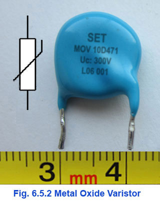
The Metal Oxide Varistor (MOV)
A common safety component used to protect mains (line) driven thyristor circuits from either of these over voltage conditions is a resistive voltage-clamping device such as the MOV (Metal Oxide Varistor), illustrated along with its circuit symbol in Fig. 6.5.2, which acts as a non-linear resistor, meaning that the relationship between current and voltage in the MOV is not linear, but changes at different applied voltages.
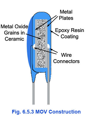
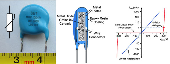
Figs. 6.5.2 to 6.5.4 MOV Construction & Characteristics
As shown in Fig. 6.5.3, a MOV looks very similar to a ceramic disc capacitor, and has some similarities in construction. The MOV has two parallel disc shaped plates just like a small ceramic capacitor, but the ceramic material between the plates of a MOV is impregnated with tiny grains of a metal oxide such as zinc oxide (ZnO) and (in much smaller amounts) another metallic oxide such as either cobalt oxide (CoO) or manganese oxide (MnO).
This has the effect that the junctions between the two types of metal oxide grains used produce many tiny diodes that are randomly oriented and so combine to form many series and parallel forward and reverse biased diode networks. Therefore when a low voltage is applied to the conducting plates, only a very small current (the reverse leakage current of the diodes) flows, but above a certain critical voltage, called the Varistor Voltage, the diode junctions within the ceramic material break down allowing a large current to flow.
Therefore the MOV has a very high resistance below the varistor voltage and a very low resistance above it. This voltage is specified for any particular MOV as the voltage at which a current of 1mA flows through the MOV.
Typical voltage/current characteristics for a MOV are shown in Fig. 6.5.4 where the MOV described by these characteristics has a varistor voltage of 300V. Therefore between -300V and +300V there is no perceptible change in current, indicating that the MOV has a resistance approaching infinity, but at higher voltages (in either polarity) than the 'Varistor Voltage' specification, a large current flows with hardly any further change in voltage. The MOV in this region therefore has a very low resistance.
To protect a thyristor, a MOV would be chosen with a varistor voltage higher than the maximum operating voltage, but lower than the break-over voltage of the thyristor.
MOV Capacitance
Because the structure of a MOV is similar to that of a ceramic capacitor, the capacitance of a MOV has a significant effect in slowing the response time of its operation. It has more capacitance than a zener diode for example, which can be an advantage or disadvantage. In protecting DC circuits the capacitance of the slower response time of a MOV can be useful in reducing the amplitude of short duration over voltage spikes. In high frequency applications such as data line protection, the extra capacitance of a MOV across the lines could severely limit its ability to pass high frequency data.
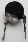
Fig. 6.5.5 MOV Destroyed
by Fire
MOV Hazards
However, although MOVs are useful in controlling over voltage events, their use does have some problems. When a voltage spike or surge occurs, the high voltage will also produce a high current through the temporarily low (but not quite zero) resistance MOV for the time that the over voltage condition exists. This means that during that time, there will also be a high current through the MOV. Therefore voltage current and time are all involved, so the spike could more properly be described as an energy spike, with the amount of energy involved measured in joules rather than simply in volts, so MOVs are rated in joules as well as in volts.
In protecting against these high-energy events the MOV must dissipate a large amount of energy in a very short time. This causes a large amount of heat to be generated in the MOV, and if this heat cannot be dissipated quickly enough, or the over voltage continues for more than a very short time, the MOV can go into thermal runaway, where the increase in temperature causes an increase in current, which in turn causes a further increase in temperature, leading to so much current that the MOV is rapidly destroyed, creating a fire risk, see Fig. 6.5.5. Even supposing the MOV is totally destroyed without catching fire, but becomes open circuit, there is then the situation that the circuit it was protecting is now unprotected against the next over voltage event.
A MOV is very effective in eliminating short spikes in voltage, provided that the voltage does not go too high or last too long, but cannot be expected to deal with events such as direct or nearby lightning strikes, nor will they survive prolonged over voltage conditions due to power surges.
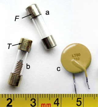
Fig. 6.5.6 MOV Protection
Extra Protection for MOVs
To minimise the fire risk in MOVs, they must in turn be protected by at least a second safety device. This may be a fuse, which will blow to cut off current to the circuit in the event of too much current flowing. Fuses can either act immediately in the case of fast blow fuses, typically marked F250mA for example on a 250mA fast blow fuse, see example (a) in Fig. 6.5.6 or after a short time of over current, often necessary to avoid the fuse blowing due to normal current surges at switch on of the equipment. Anti-surge fuses can vary in construction, but a typical anti-surge fuse is shown in example b in Fig. 6.5.6. Note the spring device inside the fuse and the letter 'T' before the indicated current rating embossed on one of the end terminals, denoting 'time delay'.
Fuses are a simple 'one off' over-current protection device; once a fuse inside a piece of electronic equipment fails, it generally requires the attention of a service technician, not just to replace the fuse but to diagnose the fault that caused the over-current. This human intervention provides an extra layer of protection in what could be a dangerous condition.
Polymer based positive temperature coefficient (PPTC) resistors (example c in Fig. 6.5.6) are also available to provide over-current protection, these components act thermally in rapid response to the extra heat caused by the over current, but instead of failing permanently like ordinary fuses, they can reset themselves after the over-current situation has ended.
Fig. 6.5.7 PPTC Over Current Protection
These devices, also called Multifuses or Polyfuses (Manufacturers names), are basically resistors made by using a polymer material impregnated with carbon granules. In PPTCs their resistance remains low at normal temperatures, as the carbon granules in contact with each other form low resistance chains across the device, but when a specified high temperature is reached, due to high current flow, the polymer expands to a point where, the carbon granules are separated and the resistance though the device rapidly increases to a very much higher value, cutting off current flow almost completely until the PPTC is allowed to cool once more. Then the carbon granules reconnect and the low resistance pathways return once more. These thermal cut off devices may be used in series with the supply, to protect the whole circuit, as shown in Fig. 6.5.7 or may be combined within the MOV (called a TMOV or thermally protected MOV) in which case the thermal protection only applies to the MOV itself. The time to trip (TtT) taken for the PPTC resistor to 'trip' into its high resistance state will typically be in a range from one millisecond to around 10 seconds. The trip time for any given device will be approximate, as it will also depend on external factors such as fault current and ambient temperature.
Gas Discharge Tubes (GDTs)
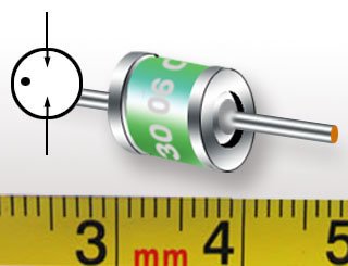
Fig. 6.5.8 Gas Discharge Tube (GDT)
MOVs are efficient at suppressing voltage spikes up to a few hundred volts but for over voltage spikes and surges induced by distant lightning strikes it is necessary to use devices such as Gas Discharge Tubes (GDTs). These surge arresters (illustrated in Fig. 6.5.8) are small ceramic or glass tubes filled with an inert gas between two electrodes, which has an almost infinite resistance up to its particular breakdown or spark-over voltage, but above this limit will conduct heavily.
GDTs are available over a range of breakdown voltages from around 75volts up to several thousands of volts, depending on the gas used, its pressure and the physical dimensions of the tube.
Fig. 6.5.9 SCR Snubber
Snubber Circuits
Another method for reducing the impact of voltage spikes on SCR operation is to use a RC snubber circuit across the SCR or triac as shown in Fig. 6.5.9. In this simple circuit the correct choice of RC time constant can reduce the amplitude of voltage spikes by diverting the energy produced by the high voltage and current into charging the capacitor over the time duration of the over voltage, by partly charging the capacitor (and therefore reducing the amplitude of the voltage across the circuit during the charge) then releasing the stored energy back to the circuit at a controlled rate via the resistor. The overall effect being to substantially reduce the amplitude of any random over voltage spikes. More information on snubber circuits is available in Thyristor Module 6.6 RC Snubber Circuits.