
Google Ads
Module 6.3
Triacs & Diacs
- After studying this section, you should be able to:
- Recognise typical triac packages:
- Understand a typical triac characteristics diagram.
- Understand the function of quadrants in triggering triacs:
- Understand the basic principles of opto triacs.
- Understand the operation of diacs.
- Understand methods and limitations for out of circuit testing of thyristors.
- Safety considerations for using medium and high voltage devices.
The Triac
Fig. 6.3.1 Triac Packages
Fig. 6.3.1 shows some typical triac packages together with the circuit symbol for a triac. The triac is a bi-directional thyristor, similar in operation to two SCRs connected in reverse parallel but using a common gate connection. Therefore the triac can conduct and be controlled during both positive and negative half cycles of the mains waveform. Instead of having positive anode and negative cathode connections however, the triac's main current carrying connections are normally labelled MT1 and MT2 signifying Main Terminals 1 and 2 (although other letters may be used) as either terminal can be positive or negative. The triac can be triggered into conduction by a pulse of current applied to the gate terminal (G). Once triggered the triac will continue to conduct until the main current reduces below the current holding threshold close to zero.
Fig. 6.3.2 Triac Characteristics
- Fig. 6.3.2 illustrates the main characteristics of the triac.
- VBO is the maximum forward or reverse voltage that the triac can tolerate before it breaks over into uncontrolled conduction.
- VDRM is the maximum repetitive peak voltage (usually the maximum peak voltage of the applied AC wave) that can be reliably tolerated.
- VGT is a range of gate voltages that will trigger conduction.
- IL is the minimum current that will cause the triac to latch and continue conducting after the gate triggering voltage is removed.
- IH is the minimum holding current below which a conducting triac will cease conduction.
Fig. 6.3.3 Triac Quadrants
Triac Quadrants
Because the gating current or pulse used to trigger the triac, may be applied whilst the MT2 terminal is either positive or negative, and the gating current or pulse may also be either positive or negative, there are four different ways to trigger the triac. These are usually described as ´Quadrants´ as shown in Fig. 6.3.3
Most triacs can be triggered in any of the four quadrants, and two of the four possible quadrants are needed to trigger conduction during the two (positive and negative) half cycles of the AC wave. Quadrants I, and III or quadrants II, and III are the favoured methods of triggering, as quadrant IV is much less sensitive to triggering because of the way the diac is constructed. So if quadrant IV is used with any of the other three quadrants, the positive and negative half cycles would need different values of trigger current, creating an unnecessary complication. Also if a triac is triggered in quadrant IV, its capability of handling any fast current changes (δI/δt) is reduced, making the triac more susceptible to damage from events such as random high current spikes and the inevitable high inrush currents when filament lamps are switched on.
An important aim in many modern designs is to combat potentially damaging over voltage spikes, and to reduce the tendency for the triac to re-trigger during the switched off portion of a cycle. This happens during each AC cycle between the time when the current drops below the holding current of the thyristor and before the next trigger pulse. Although not normally a problem when the triac is driving a resistive load such as an incandescent lamp, when used with inductive loads such as motors the load voltage and load current will quite likely not be ´in phase´ with each other, so the voltage can actually be near its peak value when the current drops to zero, (as described here) causing a large and rapid change in voltage across the triac that may cause the triac to instantly re-trigger and so switch on again so that control is lost.
Standard triacs have been used for AC control for many years, but over that time the range of different triac designs has increased enormously. Modern triac designs such as 3Q HIGH-COM (3 quadrant, high commutation) triacs from NXP/WeEn and SnubberlessTM triacs from ST Microelectronics have many advantages such as improved performance, less false triggering, usability with both resistive and inductive loads and improved switch off capabilities without the need for additional circuitry such as snubbers. Additional input conditioning is also a feature of some designs, including gate pulse conditioning such as zero crossing detectors and logic level inputs etc.
As many control functions are now carried out using microprocessors and/or logic circuits, there are also many triacs that accept logic signals for triggering rather than relying solely on traditional phase control techniques. One such triac is the 6073A Sensitive Gate triac from ON Semiconductor, which is used in the low voltage demonstration circuit in Thyristors Module 6.4.
Fig 6.3.4. The Opto Triac
Opto Triac
The materials used in the manufacture of Triacs and SCRs, like any semiconductor device, are light sensitive. Their conduction is changed by the presence of light; that's why they are normally packaged in little chunks of black plastic. However, if an LED is included within the package, it can turn on the high voltage device output in response to a very small input current through the LED. This is the principle used in Opto-Triacs and Opto-SCRs, which are readily available in integrated circuit (IC) form and do not need very complex circuitry to make them work. Simply provide a small pulse at the right time to illuminate the built in LED and the power is switched on. The main advantage of these optically activated devices is the excellent insulation (typically several thousand volts) between the low power and high power circuits. This provides safe isolation between a low voltage control circuit and high voltage high current output. Although the output current of opto triacs is usually limited to tens of milliamps, they provide useful interface when the output is used to trigger a high power triac from a low voltage opto triac.
The Diac
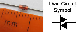
Fig. 6.3.5 DB3 Diac & Circuit Symbol
The diac is a bi-directional trigger diode (see Fig.6.3.5) that has been used for many years as the main triggering component for standard triacs. It blocks current flow when a voltage applied across it is less than its break over potential VBO (see Fig.6.3.6), but conducts heavily when the applied voltage is equal to VBO. However, unlike other diodes that conduct in one direction only, the diac has similar break over voltage in both positive or negative directions. Once the AC voltage applied to the diac reaches either +VBO or -VBO, a positive or negative current pulse is produced. The break over potential for diacs is typically around 30 to 40 volts. This action makes diacs particularly useful in triggering triacs in AC control circuits because of its ability to trigger the triac during either the positive or the negative half cycle of the mains (line) waveform. Its circuit symbol (shown in Fig. 6.3.5) is similar to that of a Triac, but without the gate terminal.
Fig. 6.3.6 Typical Diac Characteristics.
The Diac characteristics illustrated in Fig. 6.3.6 show that at voltages below VBO the diac has a high resistance, (the characteristic curve is nearly horizontal indicating that there is only a small leakage current of a few µA flowing, but once +VBO or -VBO is reached, the diac exhibits a negative resistance. Normally, Ohm's law states that an increase in current through a component with a fixed value of resistance, causes an increase in voltage across that component; however the opposite effect is happening here, the diac is exhibiting negative resistance at break-over, where the current increases sharply, although the voltage is actually reducing. The negative resistance mode lasts for a period of about 2µs, by which time the forward voltage has dropped to about 5V and the diac is passing a current of 10mA. This action is fairly (though not exactly) symmetrical in either the positive(+V) or negative regions of the characteristics.
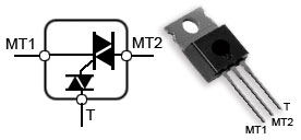
Fig 6.3.7. The Internally Triggered Triac (Quadrac)
Internally Triggered Triac (Quadrac)
There are far fewer types of diac available from component suppliers than there are triacs. Also it is easier to select the ideal diac for triggering a particular triac when it is already built in to the package. Such is the case with the ´Quadrac´ or Internally Triggered Triac illustrated in Fig. 6.3.7. These devices also reduce component count and PCB space.
Sensitive Gate Triacs
Triacs that depend on a diac for triggering have a drawback for many modern low voltage applications. The voltage required for the diac to produce a trigger pulse must be at least as equal to, or greater than its break over potential (VBO) and this is about 30V or more. However there are triacs available - Sensitive Gate Triacs - that can be triggered by much lower voltages, within the range of TTL, HTL, CMOS and OP AMP devices as well as microprocessor outputs.
A demonstration circuit for driving a sensitive gate triac is shown in Thyristor Module 6.4.
Testing Thyristors, Triacs and Diacs.
There are many pages on the internet that offer methods for testing SCRs and triacs using a multi meter. They basically involve checking the resistance of the device being tested to ascertain whether or not it is open circuit. Measuring the resistance between anode and cathode of a SCR or between the two main terminals of a triac, should indicate a very high resistance when measured in either direction by swapping round the meter probes.
In both tests the meter should register out of range resistances (usually indicated by the display showing ´1´ or ´OL´) also called infinity or infinite resistance. Similar resistance tests can be carried out by measuring the resistance, again in both directions, between the gate of an SCR and its cathode, or the gate and MT1 on a triac, and should indicate a much lower resistance, but not zero ohms.
If any of these four tests produce a reading of zero ohms it may be assumed that the component is faulty; however if the results show no faults this only PROBABLY means the component is OK. Resistance tests on these high voltage components are only of limited use and can only be relied on as a simple guide; they do not show that the device will be triggered at the correct voltage, or that the holding current is correct. SCRs and Triacs usually operate at mains (line) voltage and when they fail the results can be dramatic. At least the violent blowing of a fuse will be the usual result of a short circuit SCR or triac. It is quite possible however, for these devices to be faulty and not show any fault symptoms on an ohmmeter test. They may seem OK at the low voltages used in test meters, but still fail under mains voltage conditions. High voltage components such as SCRs and triacs may also be damaged by unseen voltage spikes or over current events.
The normal method of testing in equipment using SCRs or triacs would be the checking of voltages and waveforms if the circuit was operating, or substitution of a suspect part when damage (e.g. blown fuses) is apparent. In many cases components in power supplies or high voltage control circuitry of manufactured equipment will be designated "safety critical components" and must only be replaced using manufacturers recommended methods and components. It is common for manufacturers to specify complete "service kits" of several semiconductor devices and possibly other associated components, all of which must be replaced, since the failure of one power control device can easily damage other components in a way that is not always obvious at the time of repair.
ANY WORK ON MAINS POWERED CIRCUITS MUST BE DONE WITH THE MAINS SUPPLY FULLY DISCONNECTED. ALSO ANY CHARGE STORING COMPONENTS (e.g. CAPACITORS) SHOULD BE DISCHARGED UNLESS THIS IS ABSOLUTELY UNAVOIDABLE.
If you have not been trained in the safe working practices that are essential for work on these types of circuit DON'T DO IT! These circuits can kill!