Module 7.3
Measuring Impedance
- After studying this section, you should be able to describe:
- • Practical methods of measuring impedance.
Measuring Impedance
Because Impedance is an AC property it cannot be easily measured like resistance. Connecting an Ohm meter across the input or output of an amplifier only indicates the DC resistance. It is quite possible however to measure input and output impedance at any frequency using a signal generator, an oscilloscope (or AC voltmeter) and a decade resistance box or a variable resistor.

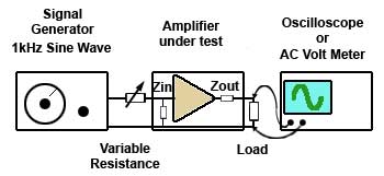
Fig 7.3.1 Measuring Input Impedance
The set up for measuring input impedance is illustrated in Fig. 7.3.1. A variable resistor or a decade resistance box is connected between the signal generator and the amplifier input and its resistance is set to zero Ohms. An oscilloscope or AC voltmeter is connected across the amplifier load (e.g. loudspeaker).
The signal generator is set to provide a sine wave output at 1kHz. The amplitude of the input signal should be adjusted so that the display on the oscilloscope is noise free (large enough) and distortion free (not too large). The display on the oscilloscope screen should be as large as is practical and set so that its amplitude and half its amplitude can be easily estimated.
The resistance at the amplifier input should then be increased until the output waveform is exactly half its previously set value. At this setting the signal is shared equally between the test resistance and the input impedance of the amplifier, meaning that the resistance and impedance are equal. After switching off and removing the test resistance, the reading of the decade box settings or measuring the variable resistor with an Ohm meter gives the value equivalent to the input impedance of the amplifier.

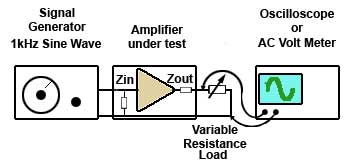
Fig 7.3.2 Measuring Output Impedance
The measurement of output impedance uses the same method as for input impedance but with different connections. In this case the amplifier load is replaced with the decade box or variable resistor. Care must be taken however, to ensure that the resistance connected in place of the load is able to dissipate sufficient power without damage. The amplifier need not be run at full power for this test.
Connect the test circuit as shown in Fig. 7.3.2 and initially the output from the amplifier should be adjusted for a display similar to that used for the input impedance test, but this time with no load connected to the output terminals. The test resistance is then connected across the output terminals and adjusted for maximum resistance before switching on the amplifier. The test resistance is reduced in value until the display indicates half the amplitude of that noted with no load. The test resistance is now the same value as the output impedance.
Google Ads


