Module 4.2
Capacitance and Resistance in a DC Circuit
- After studying this section, you should be able to describe:
- • Transient events in DC circuits.
- • Transient voltage and current relationships in a simple CR circuit
The voltage across a capacitor cannot change instantaneously as some time is required for the electric charge to build up on, or leave the capacitor plates.

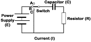
Fig.4.2.1 The CR circuit
In Fig 4.2.1, when the switch is changed from position A to position B, the capacitor voltage tries to charge to the same voltage as the battery voltage, but unlike the resistor circuit, the capacitor voltage can´t immediately change to its maximum value, which would be (E).

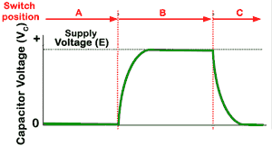
Fig 4.2.2 Capacitor Voltage
Charging and Discharging the Capacitor
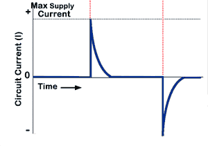
As soon as the switch reaches position B, the circuit current rises very rapidly, as the capacitor begins to charge . Although the voltage (see Fig 4.2.2) is still low, its rate of change is large and the voltage graph is initially very steep, showing that the voltage is changing in a very short time. As the capacitor charges, the rate of change of voltage slows and charge slows as the charging current (see Fig 4.2.3) falls. The curve describing the charging of the capacitor follows a recognisable mathematical law describing an exponential curve until the current is practically zero and the voltage across the capacitor is at its maximum.

Fig 4.2.3 Capacitor Current
If the switch is now changed to position C, the supply is disconnected and a short circuit is placed across C and R. This causes the capacitor to discharge through R. Immediately maximum current (see Fig 4.2.3) flows, but this time in the opposite direction to the that during charging. Again an exponential curve describes the fall of this negative current back towards zero. The voltage also falls exponentially during this time, until the capacitor is fully discharged.
Opposites
Compare the graphs describing the actions of the CR circuit described above and the LR circuits in section 4.4. Notice that the curves described are the same, but the voltage and the current curves have "changed places". These "opposite" effects of L and C will be noticeable in many of the actions described in later modules.
Google Ads


