
Module 4.5
The LR Time Constant.
- After studying this section, you should be able to describe:
- • The Time constant of an LR circuit.
- ...and carry out calculations involving
- • Time constants in a simple LR circuit.
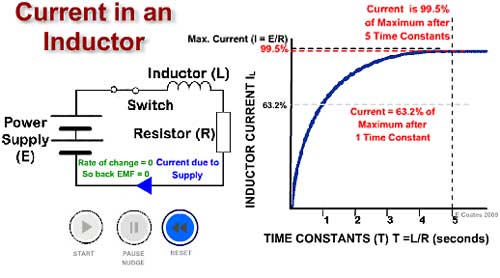
Fig. 4.5.1 The LR Time Constant.
When a current is applied to an inductor it takes some time for the current to reach its maximum value, after which it will remain in a "steady state" until some other event causes the input to change. The time taken for the current to rise to its steady state value in an LR circuit depends on:
•The resistance (R)
This is the total circuit resistance, which includes the DC resistance of the inductor (RL) itself, plus any external circuit resistance.
• The inductance of L
Which is proportional to the square of the number of turns, the cross sectional area of coil and the permeability of the core.
An Inductor opposes CHANGES in current flow
Fig. 4.5.1 The LR Time Constant
When the circuit in Fig 4.5.1 is switched on current changes rapidly from zero, this sudden change creates a rapidly expanding magnetic field around the inductor coils, and in doing so induces a voltage back into the coil. This induced voltage (called a back EMF) creates a current (the green arrowhead in the circuit diagram) flowing in the OPPOSITE direction to the original current (the blue arrowhead in the circuit diagram) applied by the battery.
See the Back EMF current and supply current change during the time illustrated by the video in Fig 4.5.1 The result of the sudden change voltage as the circuit switches on is that the rate of change in circuit curent, instead of causing a sudden increase in current from 0V to Maximum current increases at a slower rate than it would in a totally resitive circuit. If the initial rate of change of current in the LR circuit were to continue in a linear fashion, the current would reach its maximum or steady "state value" in a time (T) given by:
T = L/R seconds.
- T is the TIME CONSTANT and is measured in seconds
- L is the INDUCTANCE and is measured in Henrys
- R is the TOTAL CIRCUIT RESISTANCE and is measured in Ohms.
Seconds and Henrys are usually far too large for most electronics measurements, and milli and micro units are commonly used, but remember when calculating to convert any of these sub units to seconds or Henrys for use in formulae.
The rise in current is not linear however, but follows a curved "exponential" path, and in one time constant (indicated in Fig 4.5.1 by the vertical dotted line) the current (indicated by the horizontal dotted line) will have only risen to 63.2% of its maximum (steady state) value. After two time constants it will reach 86.5%, after 3 time constants 95% and so on until it reaches 99.5% which is regarded as its maximum value after 5 time constants.
Discharge
If the circuit is switched off, current now does not immediately fall to zero, it again falls exponentially, and after one time constant period will have reached 36.8% of the previous steady state value (i.e.the steady state value -63.2%). It is considered to reach zero in five time constant periods.
The Exponential Curve
The change of current in an inductor in response to a step change in input is exponential. For a series of equal time periods, the current charges the inductor towards its maximum value, by a percentage of the remaining difference between the present and maximum values. So although this difference continues to shrink, the extra charge built up during each time period also shrinks. The outcome of this is that the current can never ever reach the maximum!
Why 63.2%?
If the current never reaches its steady state value, this presents a problem of how to measure the time taken to fully charge. This is why the idea of a time constant, (the time it takes to charge by 63.2%) is used. Why choose 63.2% when there are easier numbers such as 50% that could be used? Well 50% would be nice but would create an awkward formula with which to calculate the time taken.
Its Simple!
It so happens that using 63.2% (which is not too different from 50%) results in a nice simple formula of L/R for the inductor time constant, and CR for the capacitor time constant. This greatly simplifies calculations, and because the current will have reached 99.5% of the steady state value after 5 time constants, this is near enough in practice to consider that the maximum value has been reached.
Google Ads