Google Ads
Module 10.4
Damping & Q Factor
- After studying this section, you should be able to:
- • Describe methods of damping in LCR parallel circuits, and relate Q factor and bandwidth.
The Effects of Resistance in LC Parallel Circuits
Ignoring resistance, the resonant frequency of a LC parallel circuit is given by the same formula as is used for LC series circuits:


Fig 10.4.1 Parallel LCR Circuit Response Curve.
Although this formula is only approximate due to the resistance in a LC parallel circuit, inaccuracies will be small at high frequencies. In practice the above formula can still be used at the higher frequencies usually encountered in electronics for both series and parallel LC circuits where the internal resistance of the inductors used is likely to be very small.
Resistance in a parallel circuit can however substantially change the graph of impedance (Z) against frequency (f).
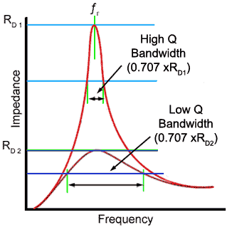
The graph of impedance against frequency in Fig 10.4.1 shows that, as frequency increases from zero towards resonance (ƒr) the impedance of the circuit increases to a maximum value (RD) at resonance and then decreases again for frequencies above resonance.The graph shows the FREQUENCY RESPONSE of the circuit.
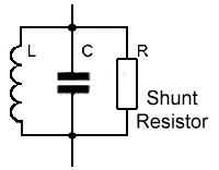
The shape of the response curve can be changed considerably by adding resistance either to the inductive branch of the circuit, e.g. increasing the internal resistance of the inductor, or by adding an external resistor called a SHUNT resistor, across the LC circuit as illustrated in Fig 10.4.2. Adding resistance by either method is called DAMPING.
Damping is frequently used in LC circuits to obtain a flatter response curve giving a wider bandwidth to the circuit, as shown by the lower curve in Fig 10.4.1. Applying damping has two major effects.
- 1. It reduces current magnification by reducing the Q factor. (R is bigger compared with XL).
- 2. It increases the BANDWIDTH of the circuit.
The bandwidth of a LC parallel circuit is a range of frequencies, either side of RD, within which the total circuit impedance is greater than 0.707 of RD.
The lower curve in Fig 10.4.1 indicates the condition where the Q factor is reduced by including a damping resistor. The maximum impedance is lower and now the area above the (green) 0.707xRD2 line covers a wider band of frequencies.

Fig 10.4.2 Damping using a shunt resistor
Bandwidth, resonant frequency and Q factor in a parallel circuit are connected by the formula:

Where B is the bandwidth (upper frequency limit − lower frequency limit) in Hz.
It can be seen from these equations that, if Q is reduced while ƒr is constant then bandwidth (B) must increase.
In a parallel circuit the amount of damping is set by both the value of the internal resistance of L and the value of the shunt resistor. The Q factor will be reduced by increasing the value of the internal resistance of L, The larger the internal resistance of the inductor, the lower the Q factor.
The shunt resistor has an opposite effect on Q, and the lower the value of R, the more the Q factor is reduced. If the value of the shunt resistor is halved, then so is the Q factor but the bandwidth is doubled.
This has the effect that if the value of the shunt resistor is halved, then so is the Q factor but the bandwidth is doubled.
Having two quite different formulae complicates the issue, but often in practice, either the internal resistance or the shunt resistance is by far the dominant effect, to the extent that the other can be ignored.


