Module 10.5

LCR Parallel Circuits Quiz


Try this quiz, based on the information you can find in Module 10. Submit your answers and see how many you get right. If you get answers wrong, just follow the hints on the answers page to find the right answer and learn more about Parallel LCR circuits as you go.

1.
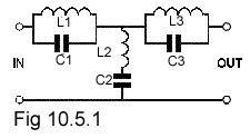
Fig 10.5.1With reference to Fig 10.5.1 the resonant frequency of the circuits L1/C1 and L3/C3 will be:

2.

In a parallel resonant circuit at resonance, the impedance is referred to as:

3.

What will be the approximate resonant frequency of a parallel LCR circuit containing L=1mH, C=1nF, R= 15Ω ?

4.

Fig 10.5.2 Phasor diagrams a-d show a single parallel resonant circuit operating at different frequencies. Which diagram shows the highest frequency?

5.

For a parallel LCR circuit at resonance, which of the following statements is true?

6.

If the Q factor of a parallel resonant circuit is halved, what will be the effect on the bandwidth?

7.

Fig 10.5.3Which of these formulae is correct for calculating the Q factor of a parallel resonant circuit?

8.

What words are missing from the following statement? The supply current phasor for IS in a parallel LCR phasor diagram at resonance will be _____________ amplitude.

9.

Fig 10.5.4With reference to Fig 10.5.4 What quantity is represented by axis A?

10.

What is the approximate Q factor of the circuit mentioned in Question 3?


Top of Page.>