Google Ads
Module 6.1
Inductive Reactance XL
- After studying this section, you should be able to describe:
- •Inductive Reactance.
- •The relationship between reactance, frequency and inductance.
- •Graphical representation of inductive reactance.
When the current in an Inductor changes, a back emf is created that opposes the change in current, and the faster the initial change in current the greater the back emf. So it is not surprising that, the faster rates of change of current that occur as the frequency of the wave increases, produce a greater back emf effect that in turn, reduces current flow more than it does at lower frequencies.
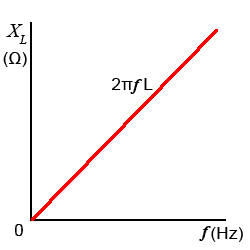
This variable opposition to current flow in an inductor, is related to the amount of the inductance, because the larger the value of inductance the greater the back emf effect produced. The opposition to current flow through an inductor is proportional to both the amount of inductance and to the frequency of the current in the inductor. This opposition to current flow is called INDUCTIVE REACTANCE (XL). The formula for Inductive Reactance multiplies the angular velocity of the AC wave by the value of Inductance:

Fig 6.1.1 Inductive Reactance

Where 2πƒ or ω is the angular velocity and L is the inductance in henries.
Like resistance, reactance it is measured in ohms, but is separate from the opposition to current caused by any internal resistance within the inductor. Large values of inductance (found in large types of inductors used at low frequencies) have higher values of internal resistance than the much smaller types of inductor used at radio frequencies and above. Inductors are basically coils of wire, and the more coils of wire an inductor has, the longer the wire will be, and the greater its value of resistance. This internal resistance cannot be separated from the inductor and must be accounted for in calculations, especially in low frequency applications that use large inductors. The small amounts of resistance present in the much smaller radio frequency inductors however, can usually be ignored.
Fig 6.1.1 shows a graph of inductive reactance against frequency for a particular value of inductance, with XL increasing with frequency in a linear fashion
Resistance in Inductors
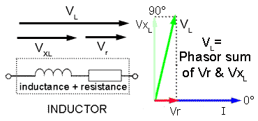
The resistance present in the wire of large inductors has a noticeable effect on current through, and voltage across an inductor. Although the effect of reactance can be calculated, it will not account for the total effect on current and voltage, the resistance must also be taken into account. The internal resistance of an inductor cannot be physically separated from the inductor as shown in Fig 6.1.2

Fig. 6.1.2 How Vr and XL affect VL In a Phasor Diagram.
Fig. 6.1.2 also shows the effect that the internal resistance of an inductor has on its phasor diagram. The voltage across the internal resistance (Vr) may be small in comparison to the voltage across the inductance, but Vr will be in phase with the reference phasor (current I) and so will produce a phase shift causing the phasor for VL to shift towards 0°.
Because VL is the phasor sum of the voltages VXL and Vr (due to both the reactance and the internal resistance of the inductor), it will also be slightly larger than the voltage (VXL) that would be calculated due to the inductance alone. This means that in practical inductor, the voltage phasor is not going to lead the current phasor by exactly +90°, the actual amount of phase shift will also depend on the amount of internal resistance. Whilst this is not a big problem with the small inductors used in high frequency applications, it does need to be considered in large, low frequency inductors where the coil has many more turns an therefore its internal resistance is greater.


