Google Ads
Module 3.2
Inductance
- After studying this section, you should be able to describe:
- • The Unit of Inductance.
- • Factors affecting Inductance.
- • Voltage and e.m.f.
- • Self Induction.
- • Back e.m.f. and its effects.
Inductance
A current generated in a conductor by a changing magnetic field is proportional to the rate of change of the magnetic field. This effect is called INDUCTANCE and is given the symbol L. It is measured in units called the henry (H) named after the American Physicist Joseph Henry (1797-1878). One henry is the amount of inductance required to produce an emf of 1 volt in a conductor when the current in the conductor changes at the rate of 1 Ampere per second. The Henry is a rather large unit for use in electronics, with the milli-henry (mH) and micro-henry (µH) being more common. These units describe one thousandth and one millionth of a henry respectively.
Although the henry is given the symbol (capital)H the name henry, applied to the unit of inductance uses a lower case h. The plural form of the henry may be henries or henrys; the American National Institute of Standards and Technology recommends that in US publications henries is used.
Factors Affecting Inductance.
The amount of inductance in an inductor is dependent on:
- a. The number of turns of wire in the inductor.
- b. The material of the core.
- c. The shape and size of the core.
- d. The shape, size and arrangement of the wire making up the coils.
Because inductance (in henries) depends on so many variable quantities, it is quite difficult to calculate accurately; numerous formulae have been developed to take different design features into account. Also these formulae often need to use special constants and tables of conversion data to work with the required degree of accuracy. The use of computer programs and computer-aided design has eased the situation somewhat. However, external effects caused by other components and wiring near the inductor, can also affect its value of inductance once it is assembled in a circuit, so when an accurate value of inductance is required, one approach is to calculate an approximate value, and design the inductor so that it is adjustable.
A typical formula for approximating the inductance value of an inductor is given below. This particular version is designed to calculate the inductance of "A solenoid wound with a single layer of turns of infinitely thin tape rather than wire, and with the turns evenly and closely spaced."

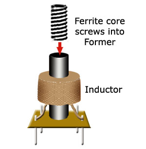
Fig. 3.2.1 A Miniature Variable Inductor.

Where:
- L is the inductance in henries.
- d is the diameter of the coil in metres.
- n is the number of turns in the coil.
- l is the length of the coil in metres.
For coils not conforming exactly to the above specification extra factors must be incorporated. Fig. 3.2.1 illustrates one way of producing a sufficiently accurate inductance, used in some HF and RF circuits. A miniature inductor is wound on a plastic former, into which a ferrite (iron dust) core is screwed sufficiently to provide a core giving the right amount of inductance.
Voltage and e.m.f.
A voltage induced into a conductor is called an e.m.f. (electro motive force) because its source is the changing magnetic field around and external to the conductor. Any externally produced voltage (including those produced by an external battery or power supply) is called an e.m.f., whilst a voltage (a potential difference or p.d.) across an internal component in a circuit is called a voltage.
Back e.m.f.
A back e.m.f.(also called a Counter e.m.f.) is an emf created across an inductor by the changing magnetic flux around the conductor, produced by a change in current in the inductor. Its value can be calculated using the formula:

Where:
- E is the induced back e.m.f. in volts
- L is the inductance of the coil in henries.
- ΔI is the change in current, in amperes.
- Δt is the time taken for the change in current, in seconds.

Notes:
Δ (Greek D – Delta) denotes a difference or change in a property.
So the formula describes the back emf as depending on the inductance (in henries) multiplied by the rate of change in current (in amperes per second).
The minus sign before L indicates that the polarity of the induced back emf will be reversed compared with the changing voltage across the conductor that originally caused the changing current and consequent changing magnetic field.
Remember that when working in practical values of milli or micro henries that all values used in the formula must be converted to the standard values of henries amperes and seconds as described in our Maths Tips booklet.
Example
Because the value of back emf depends on the rate of change of the current, it will be greatest when the fastest change occurs. For example, the rate of change is extremely fast whenever the current through an inductor is switched off; then the change can be from maximum to zero in just a few milliseconds.
Imagine that an inductor of 200mH connected across a supply of 9V is passing a current of 2amperes. When the current is switched off, it collapses to zero in 10ms, what would be the back emf generated across the coil?
E = 200mH x 2A / 10ms
or
E =200 x 10-3 x 2/10 x 10-3
= 40volts
So the back emf generated at switch off is more than 4 times higher than the supply voltage!
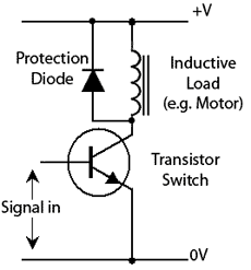
These high voltage pulses that occur when an inductive component such as a motor or relay coil is switched off, can potentially cause damage to the output transistor or integrated circuit switching the device. Therefore essential protection is provided by including a diode in the output stage as shown in Figs. 3.2.2 and 3.2.3
Back emf Protection

Fig. 3.2.2 Back e.m.f. Protection Diode.
The protection diode in Fig 3.2.2 connected across the inductor is normally reverse biased, as the voltage on its cathode, connected to the +V supply rail, will be more positive than its anode on the collector of the transistor. At switch off however, a large voltage spike of opposite polarity appears across the inductor, due to the collapsing magnetic field. For the duration of this voltage spike, the collector of the transistor could be at a higher potential than the supply, except that if this happens, the diode will become forward biased and prevent the collector voltage rising any higher than the supply rail.

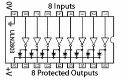
Fig. 3.2.3 Protection Diodes in the ULN2803.
Fig 3.2.3 shows a popular I.C. (ULN2803) for switching inductive loads. The outputs of the eight inverting amplifiers are each protected by a diode, having their common cathodes connected to the positive supply rail +V on pin 10.
Self-induction
The way self-induction works depends on two interlinked actions occurring simultaneously, and on each of these actions depending on the other.
Action 1.
Any conductor, in which the current is changing, will produce a changing magnetic field around it.
Action 2.
Any conductor within a CHANGING magnetic field will have a changing emf induced into it. The value of this induced emf and the amount of induced current it produces in the conductor will depend on the rate of change of the magnetic field; the faster the flux of the field changes, the greater will be the induced e.m.f. and its consequent current.
The effect of an inductor inducing an emf into itself is called Self Induction (but often referred to simply as Induction). When an inductor induces an emf into a separate nearby inductor, this is called Mutual Induction and is a property used by transformers.
The changing magnetic field created around a conductor by the changing current in the conductor causes a varying emf to be set up across that conductor. This varying emf in turn produces a varying current flowing in the opposite direction to the original current. The changes in this current therefore oppose the changes in the original current.
The effect of Action 2 is therefore to limit the changes occurring because of Action 1. If the original current is increasing, the induced current will slow the rate of increase. Similarly, if the original current is decreasing, the induced current will slow the rate of decrease. The overall result of this is to decrease the amplitude of the AC current through the inductor and so also reduce the amplitude of the AC voltage across the inductor.
Because the strength of the magnetic field set up by the original current is dependent on the rate (speed) of change of current, an inductor reduces the flow of alternating current (AC) more at high frequencies than at low. This limiting effect produced by the induced emf will be greater at higher frequencies because at high frequencies, the current and therefore the flux is changing more rapidly. The name given to this effect is Inductive Reactance.
Inductive Reactance.
Reactance produces an opposition to the flow of alternating current. Like resistance, it is measured in Ohms, but because resistance has the same value at any frequency and the opposition to AC found in inductors varies with frequency, it cannot be called resistance. Instead, it is called Reactance (X). Capacitors also have the property of reactance but they respond to frequency in a different way, therefore there are two types of reactance; inductors have Inductive Reactance (XL), and capacitors have Capacitive Reactance (XC).


